Relay Board 32x10A
Changes from previous version
This is initial version - previous versions was only for testing purposes.
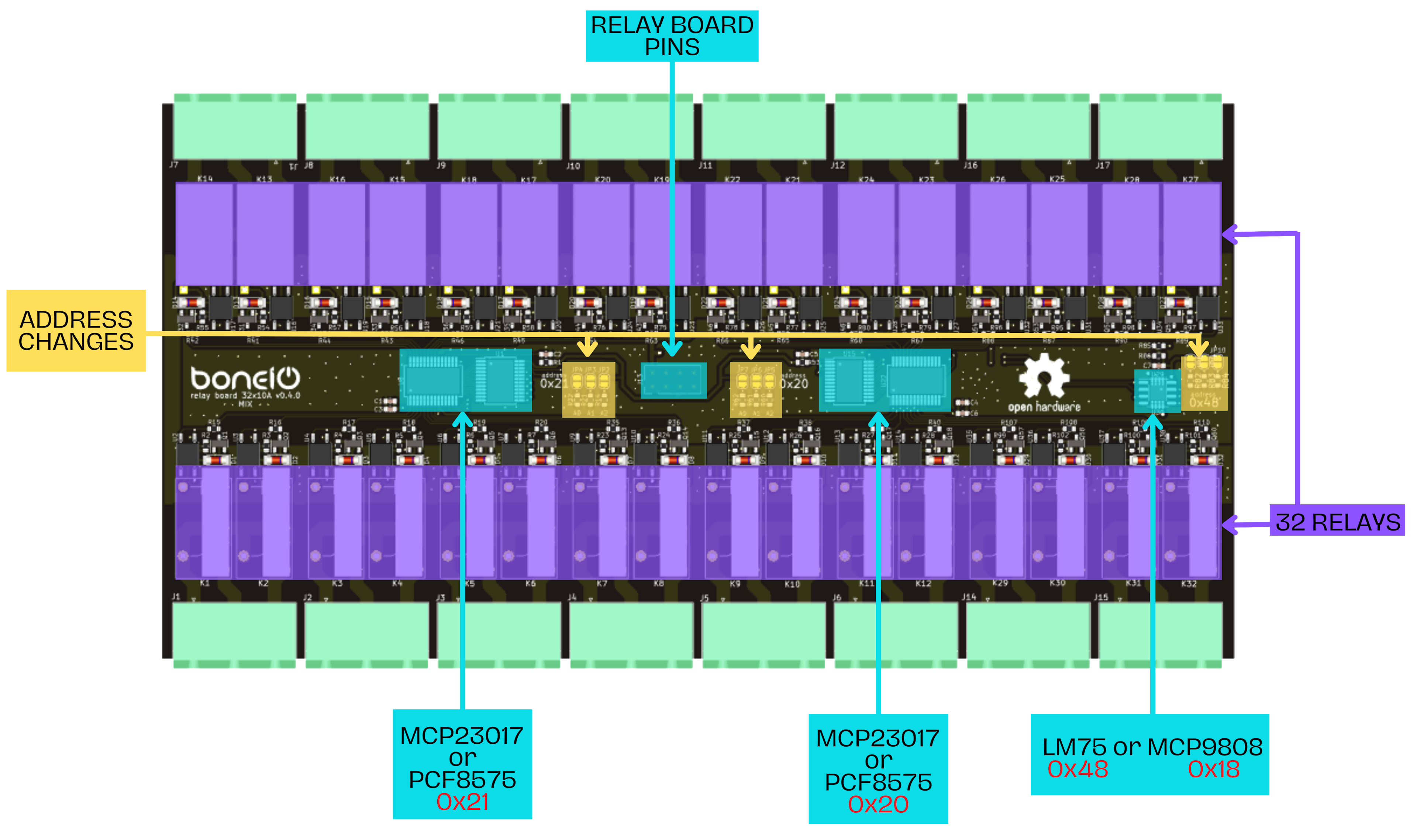
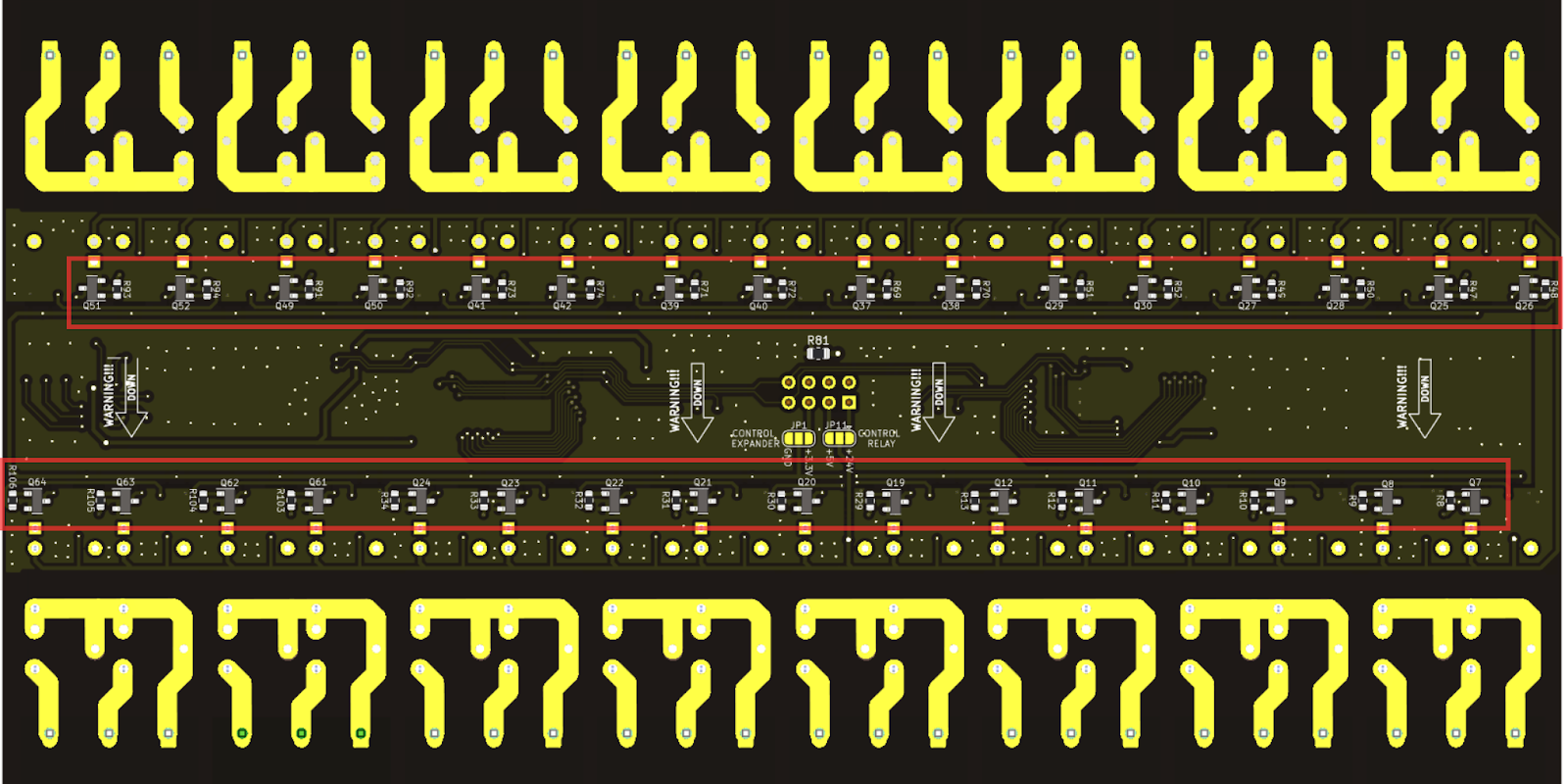
Top view
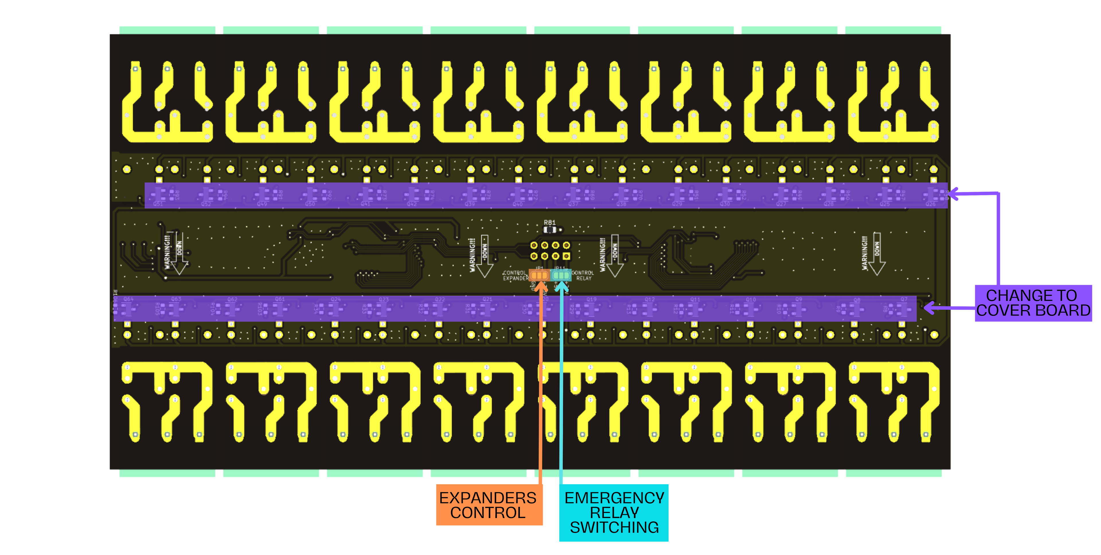
Bottom view
I2C bus
Connection with input board is established by I2C bus available on input board. On Relay board there are LM75 or MCP9808 temperature sensors.
If there are note or column according I2C bus; it applies only to newer version of Input Board ESP (>= v0.5). For all other boards there is single I2C bus
I2C bus devices
| Name | I2C bus* | Address |
|---|---|---|
| LM75 | i2c_b | 0x48 |
| MCP9808 | i2c_b | 0x18 |
| MCP23017 or PCF8575 (outputs) | i2c_b | 0x20 |
| MCP23017 or PCF8575 (outputs) | i2c_b | 0x21 |
Output relays
The outputs are divided into 16 connectors, each connector has one separate per COM connector and two relay outputs such as OUT_1 and OUT_2. COM is connected only for the outputs for a particular connector.
Expander configuration
It is available in MCP23017 or PCF8575 expander versions. For both pins are the same and if buses are divded those are available on the i2c_b bus.
| Output | Address |
|---|---|
| OUT_1 | 0x21 |
| OUT_2 | 0x21 |
| OUT_3 | 0x21 |
| OUT_4 | 0x21 |
| OUT_5 | 0x21 |
| OUT_6 | 0x21 |
| OUT_7 | 0x21 |
| OUT_8 | 0x21 |
| OUT_9 | 0x20 |
| OUT_10 | 0x20 |
| OUT_11 | 0x20 |
| OUT_12 | 0x20 |
| OUT_13 | 0x20 |
| OUT_14 | 0x20 |
| OUT_15 | 0x20 |
| OUT_16 | 0x20 |
| OUT_17 | 0x21 |
| OUT_18 | 0x21 |
| OUT_19 | 0x21 |
| OUT_20 | 0x21 |
| OUT_21 | 0x21 |
| OUT_22 | 0x21 |
| OUT_23 | 0x21 |
| OUT_24 | 0x21 |
| OUT_25 | 0x20 |
| OUT_26 | 0x20 |
| OUT_27 | 0x20 |
| OUT_28 | 0x20 |
| OUT_29 | 0x20 |
| OUT_30 | 0x20 |
| OUT_31 | 0x20 |
| OUT_32 | 0x20 |
Relay
Board has relays with a 24V coil. When using a 4A SSR, there is need of solder the Emergency Relay Switching jumper to 5V (be sure to read the instructions for changing the jumper before doing it!).
Posible relay types
There are several relay types possible to use with this Relay board.
HF32F-G
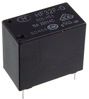
HF32FV-G
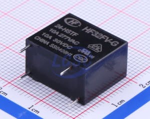
HF49FD
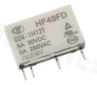
SSR 4A
For a miniature electromagnetic relay, special care should be taken when using with LED lighting.
LED bulbs create a large electrical spike when turned on, which can cause the relay contacts to stick together. In such cases, we recommend using an RC extinguisher or an external relay (contactor)
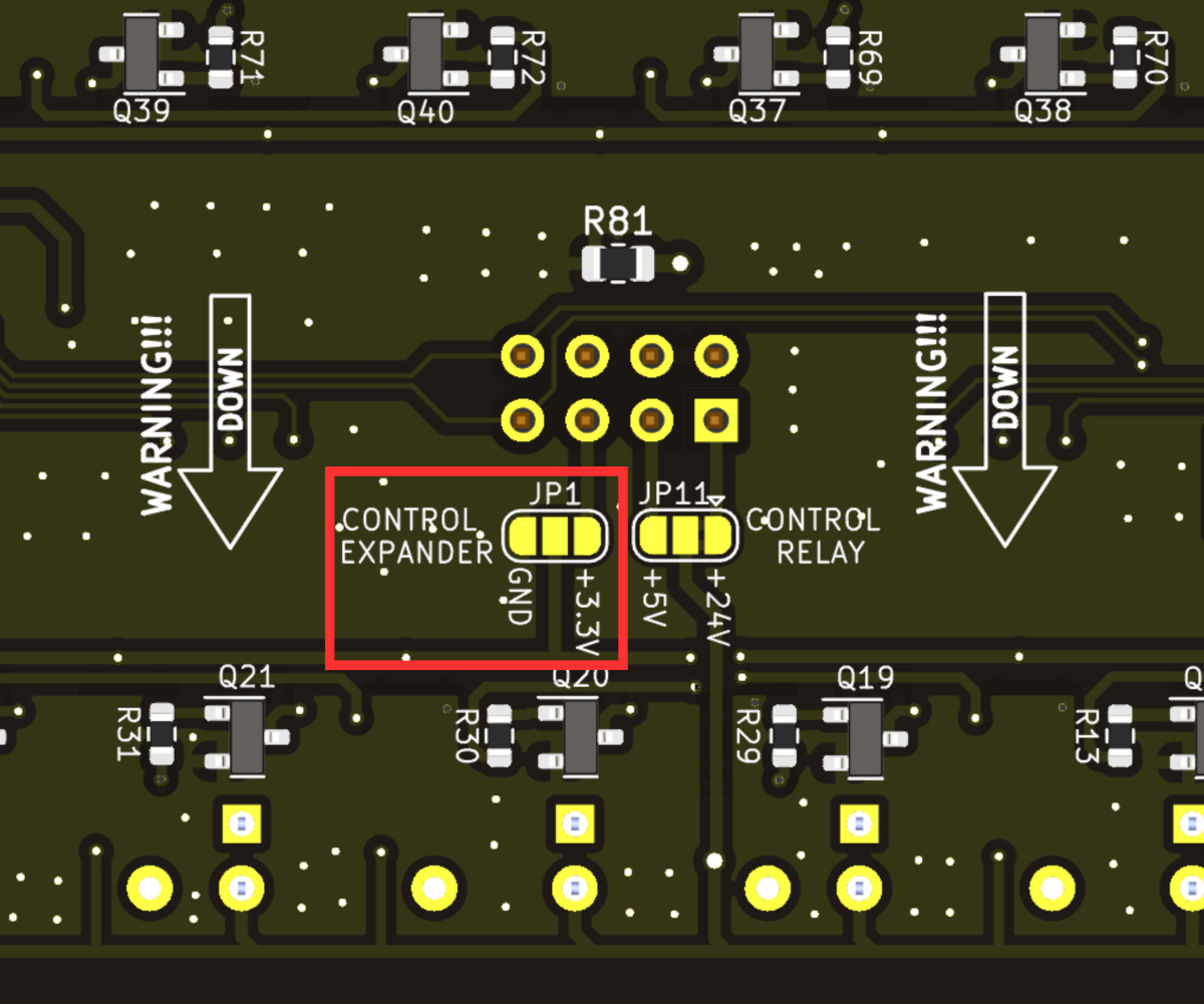
Expanders Control
Using jumpers, you can control the selection of expanders. A jumper connected to GND gives you control of MCP23017 expanders, and a jumper connected to 3.3V gives you control of PCF8575 expanders
| Control | Jumper |
|---|---|
| MCP23017 | GND |
| PCF8575 | 3.3V |
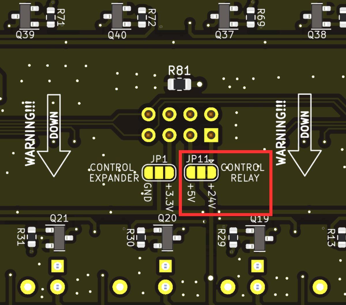
Emergency Relay Switching
The jumper is permanently connected to +24V, as it is recommended to use relays with 24V coil. It is possible to break the 24V connection and connect the jumper to 5V. It is then necessary to use relays with 5V coil, though is not recommended
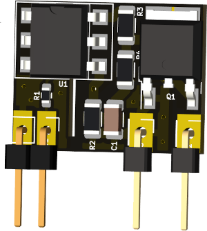
Cover board option
Soldering a BC817-40 transistor and a 4.7k resistor at these locations will protect the board from simultaneous tripping of two relays on the connectors in the same time. When the OUT_1 relay is tripped, the protection works on the OUT_2 relay and other way around, this works on each connector with outputs. The protection works on 32 relays after all components are soldered.
Schematic and PCB
The schematic and PCB image can be downloaded github :