Relay Board 24x16A
Changes from previous version
This is initial version - previous versions were only for testing purposes.
Main improvements:
- switched to i2c communication
- added temp sensor
- added degson connectors
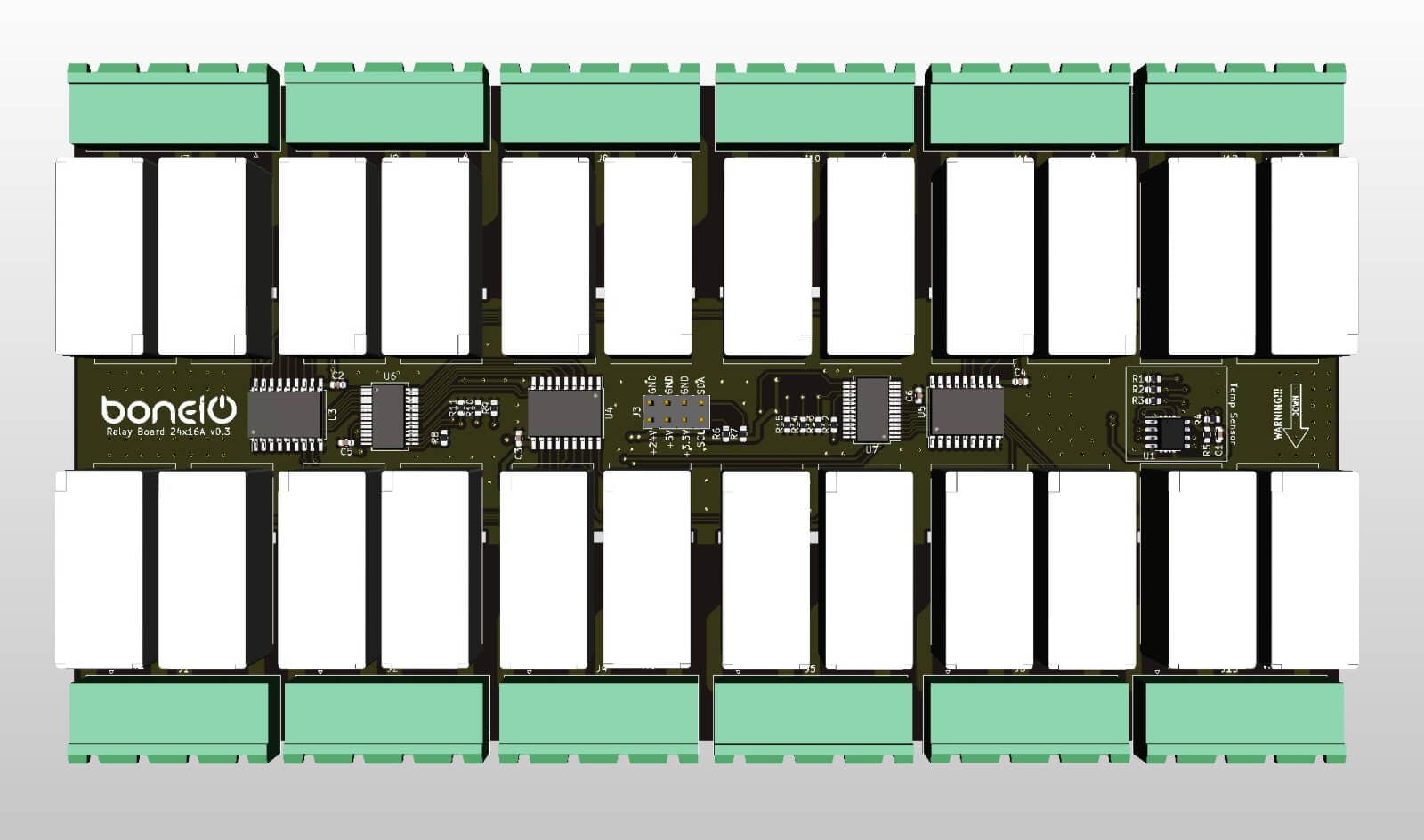
Top
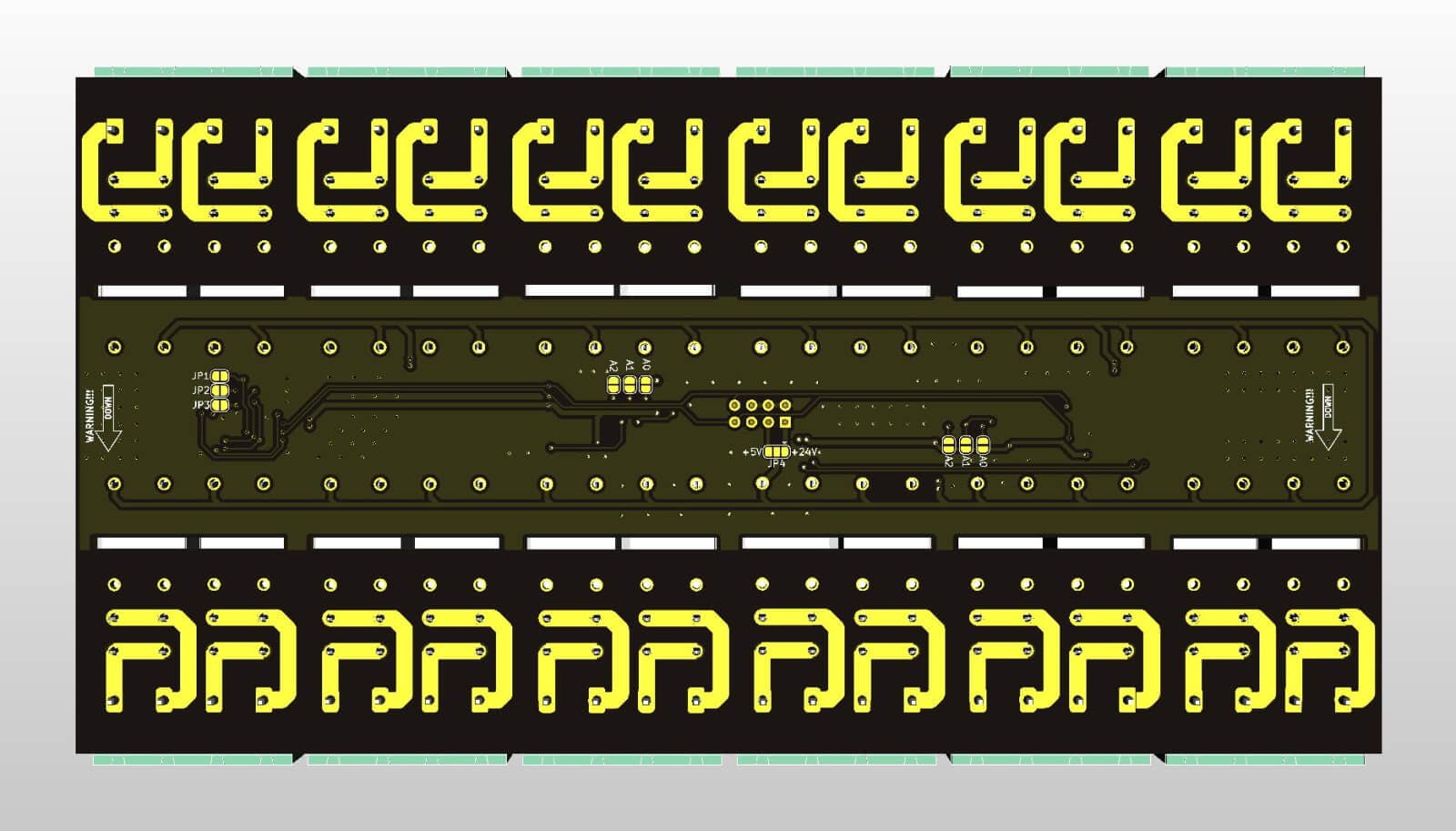
Bottom
Specification
- 24 x 16A Relays (RM85)
- Temp Sensor (MCP9808 or LM75)
- i2c Interface (MCP23017)
Bill of Materials
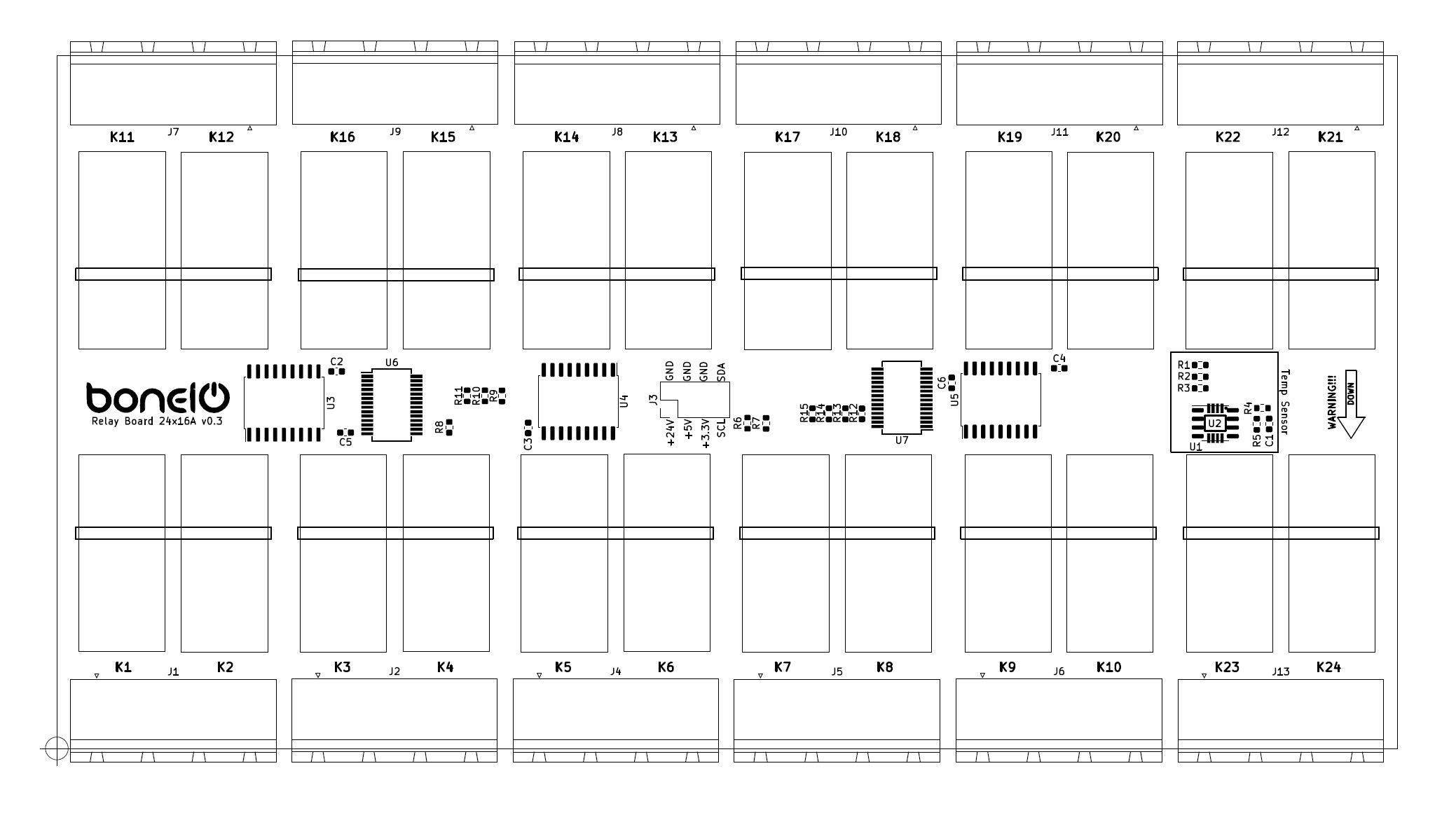
| Id | Designator | Package | Quantity | Designation |
|---|---|---|---|---|
| 1 | R5, R10, R6, R4 | R_0603_1608Metric | 4 | 4.7k |
| 2 | J2, J4, J5, J6, J7, J11, J1, J8, J9, J10, J12, J13 | PhoenixContact_GMSTBA_2,5_4-G_1x04_P7.50mm_Horizontal | 12 | Screw_Terminal_01x04 |
| 3 | U5, U3, U4 | SOIC-18W_7.5x11.6mm_P1.27mm | 3 | ULN2803A |
| 4 | C2, C3, C4, C1, C5, C6 | C_0603_1608Metric | 6 | 100n |
| 6 | J3 | PinHeader_2x04_P2.54mm_Vertical | 1 | Conn_02x04_Odd_Even |
| 7 | U2 | SOP65P490X110-8N | 1 | MCP9808-E_MS |
| 8 | U6, U7 | SSOP-28_5.3x10.2mm_P0.65mm | 2 | MCP23017_SS |
| 9 | K1, K2, K3, K4, K5, K6, K7, K8, K9, K10, K11, K12, K13, K14, K15, K16, K17, K18, K19, K20, K21, K22, K23, K24 | RM852011351024 | 24 | RM85-2011-35-1024 |
| 10 | R7, R8, R9, R11, R12, R13, R1, R2, R3 | R_0603_1608Metric | 9 | 10k |
| 11 | U1 | SO-8_3.9x4.9mm_P1.27mm | 1 | LM75_SO8 |
| 12 | SW1, SW2, SW3 | SW_DIP_SPSTx03_Slide_Omron_A6S-310x_W8.9mm_P2.54mm | 3 | SW_DIP_x03 |
| 13 | D2, D12, D22, D19, D7, D9, D10, D20, D16, D4, D17, D5, D18, D21, D1, D13, >D23, D11, D3, D8, D15, D24, D14, D6 | D_SMA | 24 | LL4148 |
Repository
Everything about this board you will find here: https://github.com/boneIO-eu/relay_board_24x16A
I2C Configuration
How to find config pins?
On every output board you will find some pins to configure I2C addresses of two MCP23017 expanders and one temperature sensor. In v0.2 it was placed on the top layer of the board, but from v0.3 you will find it on the back side.
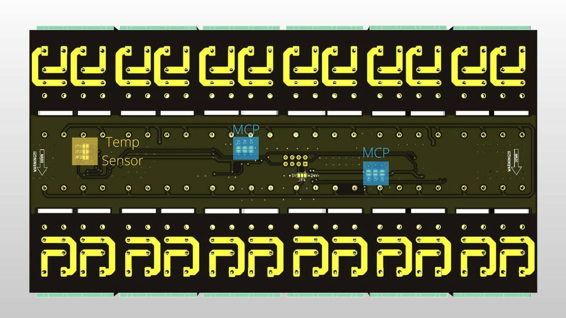
To configure address of either mcp or temp sensor you have to solder pads in proper order.
MCP23017 Configuration
| Chip Address | A2 | A1 | A0 | I2C Address |
|---|---|---|---|---|
| 000 | 0x20 | |||
| 001 | Soldered | 0x21 | ||
| 010 | Soldered | 0x22 | ||
| 011 | Soldered | Soldered | 0x23 | |
| 100 | Soldered | 0x24 | ||
| 101 | Soldered | Soldered | 0x25 | |
| 110 | Soldered | Soldered | 0x26 | |
| 111 | Soldered | Soldered | Soldered | 0x27 |
Temp Sensor Configuration
| Chip Address | A2 | A1 | A0 | I2C Address | Alternative I2C Address |
|---|---|---|---|---|---|
| 000 | 0x18 | 0x48 | |||
| 001 | Soldered | 0x19 | 0x49 | ||
| 010 | Soldered | 0x1A | 0x4A | ||
| 011 | Soldered | Soldered | 0x1B | 0x4B | |
| 100 | Soldered | 0x1C | 0x4C | ||
| 101 | Soldered | Soldered | 0x1D | 0x4D | |
| 110 | Soldered | Soldered | 0x1E | 0x4E | |
| 111 | Soldered | Soldered | Soldered | 0x1F | 0x4F |
Checking if it works
To check if your configuration works properly you have to use i2cdetect tool
i2cdetect -r -y 2
The output ow this command will be like this:
debian@beaglebone:~$ i2cdetect -y -r 2
     0  1  2  3  4  5  6  7  8  9  a  b  c  d  e  f
00:          -- -- -- -- -- -- -- -- -- -- -- -- --
10: -- -- -- -- -- -- -- -- -- -- -- -- -- -- -- --
20: 20 21 -- -- -- -- -- -- -- -- -- -- -- -- -- --
30: -- -- -- -- -- -- -- -- -- -- -- -- 3c -- -- --
40: -- -- -- -- -- -- -- -- 48 -- -- -- -- -- -- --
50: -- -- -- -- -- -- -- -- -- -- -- -- -- -- -- --
60: -- -- -- -- -- -- -- -- 68 -- -- -- -- -- -- --
70: -- -- -- -- -- -- -- --