Input Board ESP

Features
- Power supply 24V DC
- 35 inputs controlled by 24V DC (possibility of connecting switches, detectors, reed switches)
- Outputs (number depends on the Relay Board used)
- I2C bus (expandable with an expansion module or various types of sensors)
- 1-WIRE bus (DS18b20 temperature sensors can be connected)
- CAN bus
- RS485
- GPIO4 ESP connector (pull-up 4.7k to 3.3V)
- 2 ADC
- Clock RTC
- INA219 bidirectional current/power monitor of the board
- Ethernet 10/100Mbps
- USB-C (port designed for software uploads)
- 1.3” OLED display
- Button MENU
- Buzzer
- DIP Switch
Repository
Everything about this board you will find here: https://github.com/boneIO-eu/input_board_ESP
Appearance
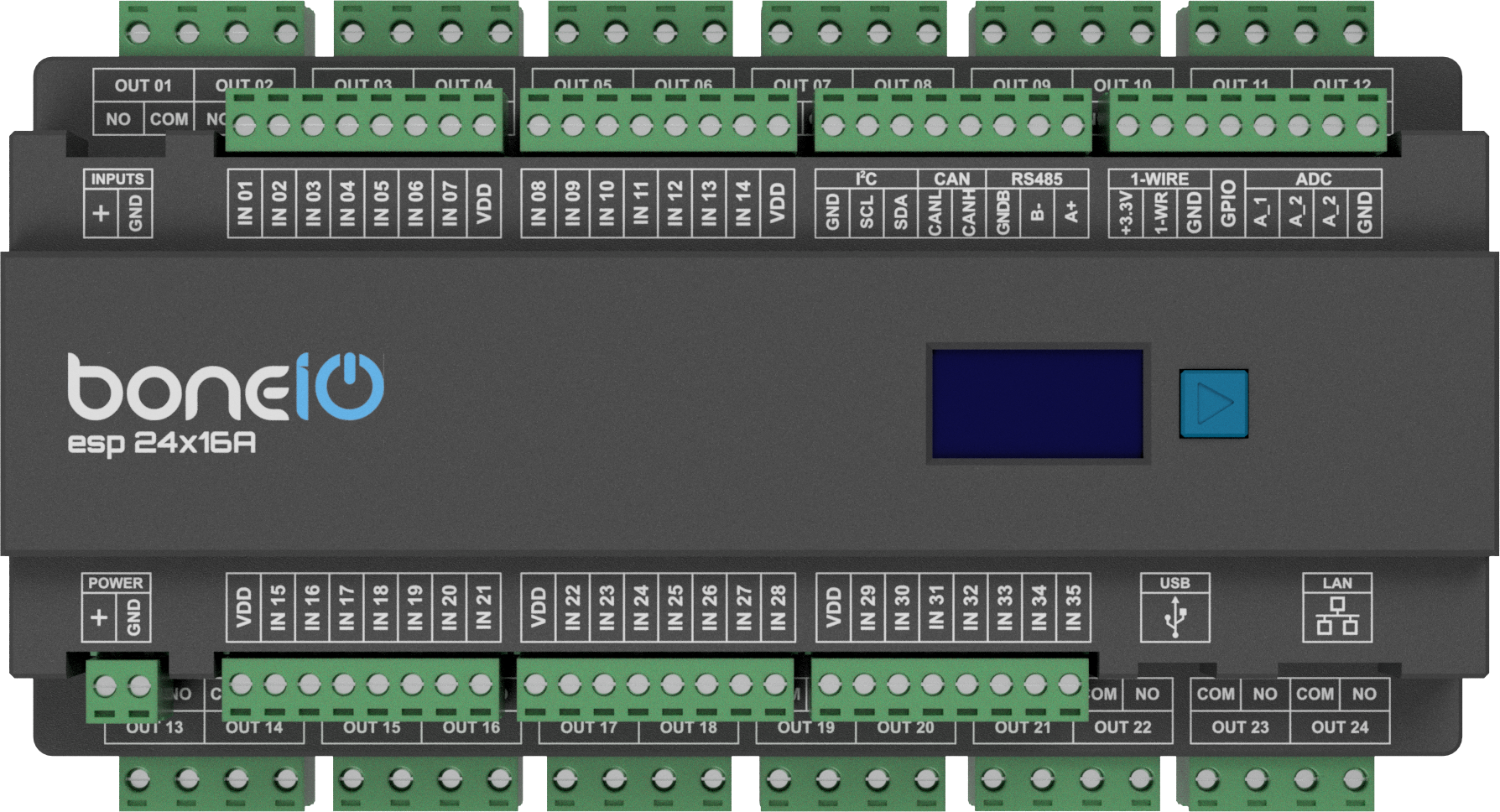
The boneio ESP controller has a housing printed on a 3D printer, the material it was printed from is PET-G. Descriptions for the case available for printing were also designed, as well as the front of the case made of brushed aluminum printed with the LOGO of our product. The descriptions are available here:
Documentation
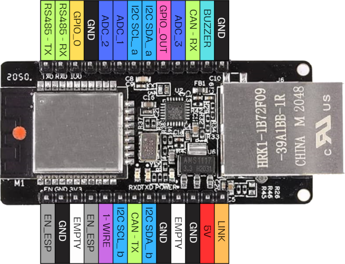
WT32-ETH01
The WT32-ETH01 chip is responsible for the brain in the controller, where the ESP32 is the control processor, and the embedded Ethernet, which is controlled by the LAN8720 chip that allows the controller to connect to a LAN. With the LAN connection, the controller communicates via ESPHOME API or MQTT with a control system such as Home Assistant.
I2C bus
The i2c bus is divided into 2 buses. The first i2c bus (bus_a) is located on pins GPIO14 (SDA) and GPIO15 (SCL). The second i2c bus (bus_b) is located on pins GPIO17 (SDA) and GPIO33 (SCL). The buses operate at a frequency of 100Mhz.
| I2C_bus | I2C_A | I2C_B |
|---|---|---|
| SDA | GPIO14 | GPIO17 |
| SCL | GPIO15 | GPIO33 |
I2C Devices
| ID | I2C Bus | Address |
|---|---|---|
| INA219 | i2c_a | 0x40 |
| OLED | i2c_b | 0x3c |
| Clock RTC | i2c_a | 0x68 |
| MCP23017 or PCF8575 (inputs) | i2c_a | 0x20 |
| MCP23017 or PCF8575 (inputs) | i2c_a | 0x21 |
| PCF8574 (inputs) | i2c_a | 0x22 |
| LM75 | i2c_b | 0x48 |
| MCP9808 | i2c_b | 0x18 |
| MCP23017 or PCF8575 (outputs) | i2c_b | 0x20 |
| MCP23017 or PCF8575 (outputs) | i2c_b | 0x21 |
| external bus | i2c_b | - |
INA219
The INA219 is a comprehensive power monitoring solution that measures with 1% accuracy and communicates digitally with the host via an I2C interface. It is capable of measuring current and voltage on the high-voltage side up to 26 V and 3.2 A. A precision current amplifier measures the voltage through a 0.1-ohm, 1% detection resistor (shunt) to determine the current flowing. The combined voltage and current measurements allow power calculation, making the INA219 ideal for tracking boneio module and power measurements.
0x401.3” OLED display
A module with a 1.3” OLED display with a resolution of 128 x 64 pixels, thanks to the SH1106 controller and communication via the I2C bus
0x3cClock RTC
The controller has a DS1307 real-time clock, whose voltage is supplied by a CR1220 round battery. It allows you to read the time in hours, minutes and seconds, the date: month, day, year.
0x68Digital inputs
The operation of digital inputs is based on applying VDD voltage to the IN_1 to IN_35 pin. There is a voltage of +24V or GND on the VDD pin by setting the DIP SWITCH respectively.
Configuration of MCP23017 or PCF8575 and PCF8574 expander pins on the i2c_a bus :
| Input ID | I2C Address | PIN Number for MCP23017 | PIN Number for PCF8575/PFC8574 |
|---|---|---|---|
| IN_1 | 0x20 | A0 | P0 |
| IN_2 | 0x20 | A1 | P1 |
| IN_3 | 0x20 | A2 | P2 |
| IN_4 | 0x20 | A3 | P3 |
| IN_5 | 0x20 | A4 | P4 |
| IN_6 | 0x20 | A5 | P5 |
| IN_7 | 0x20 | A6 | P6 |
| IN_8 | 0x20 | B0 | P10 |
| IN_9 | 0x20 | B1 | P11 |
| IN_10 | 0x20 | B2 | P12 |
| IN_11 | 0x20 | B3 | P13 |
| IN_12 | 0x20 | B4 | P14 |
| IN_13 | 0x20 | B5 | P15 |
| IN_14 | 0x20 | B6 | P16 |
| IN_15 | 0x21 | A0 | P0 |
| IN_16 | 0x21 | A1 | P1 |
| IN_17 | 0x21 | A2 | P2 |
| IN_18 | 0x21 | A3 | P3 |
| IN_19 | 0x21 | A4 | P4 |
| IN_20 | 0x21 | A5 | P5 |
| IN_21 | 0x21 | A6 | P6 |
| IN_22 | 0x21 | B0 | P10 |
| IN_23 | 0x21 | B1 | P11 |
| IN_24 | 0x21 | B2 | B12 |
| IN_25 | 0x21 | B3 | P13 |
| IN_26 | 0x21 | B4 | P14 |
| IN_27 | 0x21 | B5 | P15 |
| IN_28 | 0x21 | B6 | P16 |
| IN_29 | 0x22 | n/a | P_0 |
| IN_30 | 0x22 | n/a | P_1 |
| IN_31 | 0x22 | n/a | P_2 |
| IN_32 | 0x22 | n/a | P_3 |
| IN_33 | 0x22 | n/a | P_4 |
| IN_34 | 0x22 | n/a | P_5 |
| IN_35 | 0x22 | n/a | P_6 |
Pins to connect the output board
Pins are used to connect the lower board with relays and others.
USB-C
The controller uses USB/CH340 to connect to a computer and program the drivers. It uses a mini-USB connector for the more modern Type-C, and CH340C as a programmer.
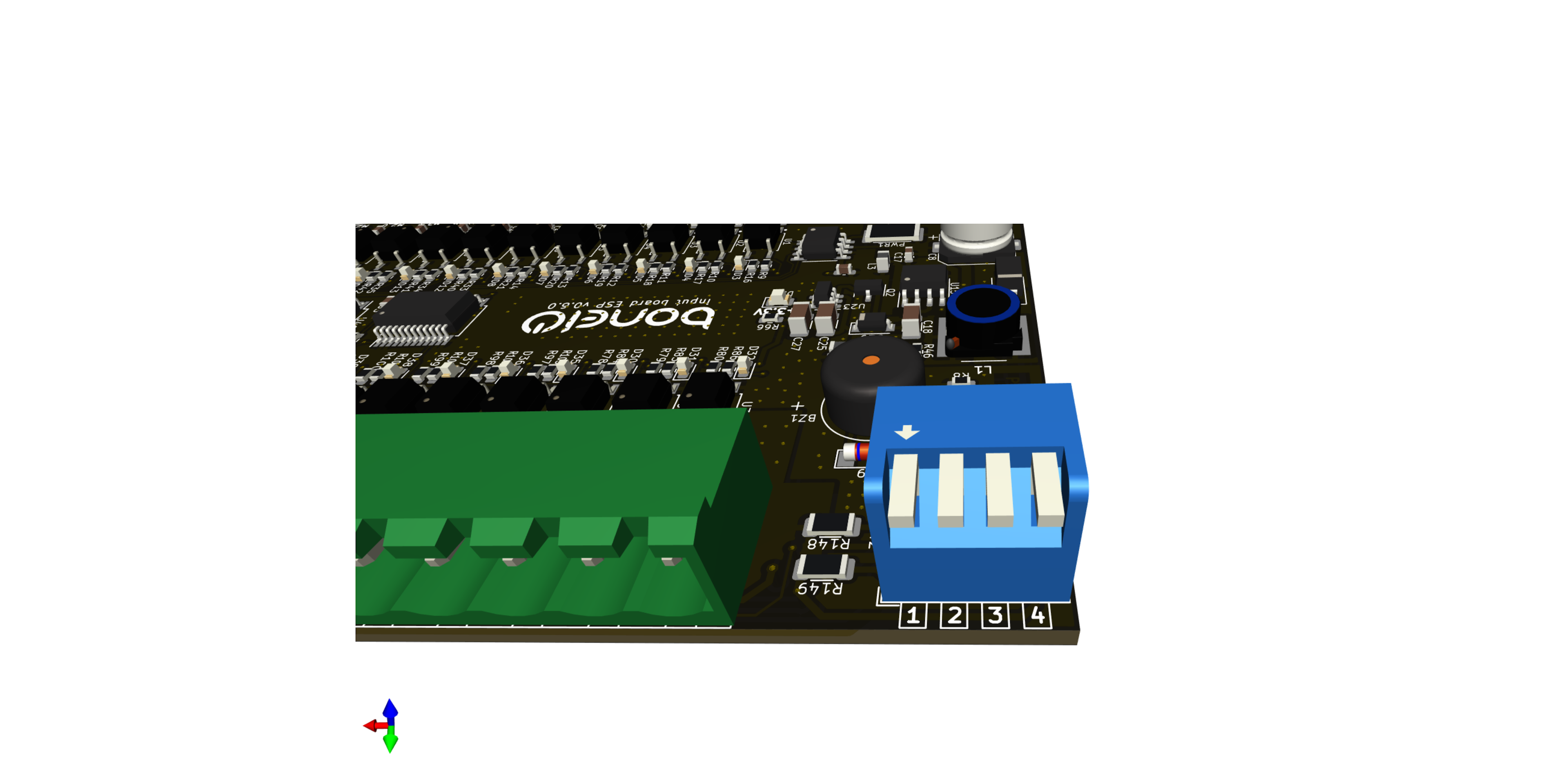
Dip Switch
With the DIP SWITCH, you can set the control of the digital inputs. Setting pins 3 and 4 to ON and 1 and 2 to OFF sets +24V control and setting pins 1 and 2 to ON and 3 and 4 to OFF is GND control.
| Control | ON | OFF |
|---|---|---|
| +24V | 3 and 4 | 1 and 2 |
| GND | 1 and 2 | 3 and 4 |
Buzzer
The high-pitched buzzer is very useful, as it is possible to notify users of various events easily and with the standard controller tools.
MENU Button
The MENU button is used to operate the OLED display and check the controller’s parameters.
The button is located on the i2c_a bus from the PCF8574 on pin P_7
Analog Inputs
Boneio input board has 2 analog inputs, a voltage divider 0 - 24V has been made . These signals go directly to the inputs of the WT32-ETH01 microcontroller.
| Input Name | GPIO Number | Voltage |
|---|---|---|
| A_1 | GPIO39 | 0 - 24V |
| A_2 | GPIO36 | 0 - 24V |
External GPIO pin
External GPIO pin to which you can connect e.g. WS2812, WS2815 or others
1-Wire
The 1-WIRE bus is suitable for DS18b20 temperature sensors.
RS485
With RS485, you can connect various devices over modbus protocol, such as energy meters or other.
| UART | GPIO |
|---|---|
| TXD | GPIO1 |
| RXD | GPIO3 |
CAN bus
With the CAN bus, various devices can be connected through the protocol.
| UART | GPIO |
|---|---|
| TXD | GPIO5 |
| RXD | GPIO35 |
Schematic and PCB
The schematic and PCB image can be downloaded github :
https://github.com/boneIO-eu/input_board_esp
Example configuration
A sample configuration of the fixture can be downloaded on Github. Make sure you look in branch of your board version.
https://github.com/boneIO-eu/esphome/tree/input_board_v_0_5
Front labels
You can download PDF with front labels from here: