Input Board Black v0.3
Features
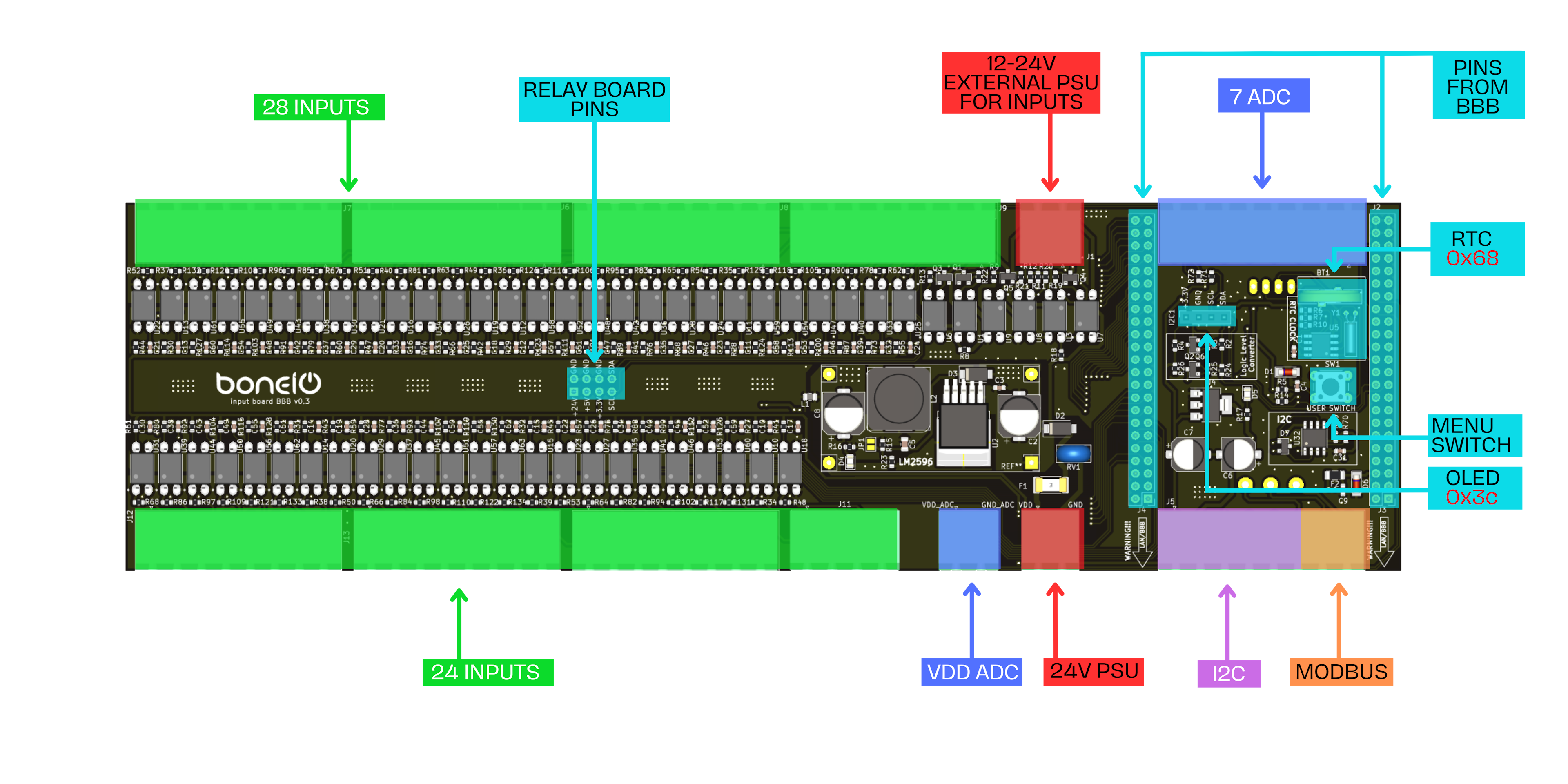
- Power supply 24V DC
- 12-24V External PSU for inputs
- 52 Inputs
- Relay Board pins (outputs)
- I2C bus
- RS485/Modbus
- 7 ADC
- Clock RTC
- Ethernet 10/100Mbps
- 1.3” OLED display
- Button MENU
Repository
Everything about this board you will find here: https://github.com/boneIO-eu/input_board_bbb/tree/v0.3
Appearance

boneio Black (formerly BBB) controller has a housing printed on a 3D printer, the material it was printed from is PET-G. Descriptions for the case available for printing were also designed, as well as the front of the case made of brushed aluminum printed with the LOGO of our product.
Descriptions label
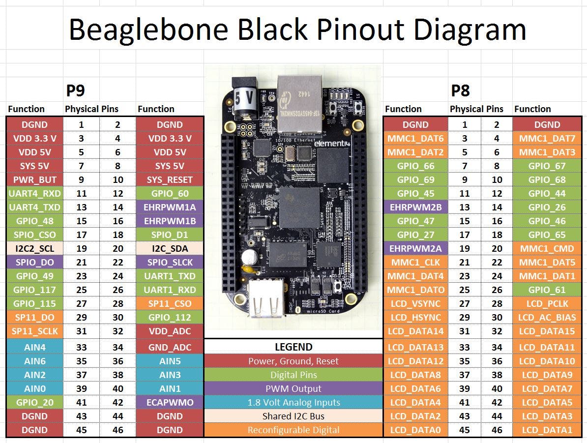
Beaglebone Black
Beaglebone Black is the brain in the controller, It is based on a Sitara AM3358 ARM Cortex-A8 processor clocked at 1 GHz. It is equipped with 512 MB of RAM and 4 GB of eMMC embedded memory, as well as built-in Ethernet which allows the controller to connect to a LAN.
With the LAN connection, the controller communicates MQTT with a control system such as Home Assistant. The controller’s operating system is based on Debian Linux
I2C bus
The i2c bus is assigned to pins:
| I2C_bus | GPIO |
|---|---|
| SDA | P9_20 |
| SCL | P9_19 |
I2C Devices
| ID | Address |
|---|---|
| OLED | 0x3c |
| Clock RTC | 0x68 |
| LM75 | 0x48 |
| MCP9808 | 0x18 |
| MCP23017 outputs | 0x20 |
| MCP23017 outputs | 0x21 |
| external bus | - |
1.3” OLED display
A module with a 1.3” OLED display with a resolution of 128 x 64 pixels, thanks to the SH1106 controller and communication via the I2C bus
0x3cClock RTC
The controller has a DS1307 real-time clock, whose voltage is supplied by a CR1220 round battery. It allows you to read the time in hours, minutes and seconds, the date: month, day, year.
0x68Digital inputs
The operation of the digital inputs is by applying VDD voltage to the IN_1 to IN_49 pin. There is a voltage of +24V on the VDD pin, or by setting the DIP SWITCH accordingly, the 12-24V PSU external for inputs can be used.
Table below presents which boneIO Input is PIN on BeagleBone Black and in which mode it can work.
Pin MAP
| INPUT BOARD PIN | BEAGLEBONE PIN | MODES |
|---|---|---|
| IN_1 | P8_37 | gpio_pu |
| IN_2 | P8_38 | gpio_pu |
| IN_3 | P8_39 | gpio, gpio_pd |
| IN_4 | P8_40 | gpio, gpio_pd |
| IN_5 | P8_41 | gpio, gpio_pd |
| IN_6 | P8_42 | gpio, gpio_pd |
| IN_7 | P8_43 | gpio, gpio_pd |
| IN_8 | P8_44 | gpio, gpio_pd |
| IN_9 | P8_45 | gpio_pu |
| IN_10 | P8_46 | gpio_pu |
| IN_11 | P9_42 | gpio, gpio_pd |
| IN_12 | P9_31 | gpio, gpio_pd |
| IN_13 | P9_30 | gpio, gpio_pd |
| IN_14 | P9_29 | gpio, gpio_pd |
| IN_15 | P9_28 | gpio, gpio_pd |
| IN_16 | P9_27 | gpio, gpio_pd |
| IN_17 | P9_25 | gpio, gpio_pd |
| IN_18 | P9_23 | gpio, gpio_pd |
| IN_19 | P9_22 | gpio_pu |
| IN_20 | P9_21 | gpio_pu |
| IN_21 | P9_18 | gpio, gpio_pd |
| IN_22 | P9_17 | gpio, gpio_pd |
| IN_23 | P9_16 | gpio, gpio_pd |
| IN_24 | P9_15 | gpio, gpio_pd |
| IN_25 | P9_14 | gpio, gpio_pd |
| IN_26 | P8_7 | gpio, gpio_pd |
| IN_27 | P8_8 | gpio, gpio_pd |
| IN_28 | P8_9 | gpio, gpio_pd |
| IN_29 | P8_36 | gpio_pu |
| IN_30 | P8_35 | gpio_pu |
| IN_31 | P8_34 | gpio_pu |
| IN_32 | P8_33 | gpio_pu |
| IN_33 | P8_32 | gpio_pu |
| IN_34 | P8_31 | gpio_pu |
| IN_35 | P8_30 | gpio, gpio_pd |
| IN_36 | P8_29 | gpio, gpio_pd |
| IN_37 | P8_28 | gpio, gpio_pd |
| IN_38 | P8_27 | gpio, gpio_pd |
| IN_39 | P8_26 | gpio, gpio_pd |
| IN_40 | P8_19 | gpio, gpio_pd |
| IN_41 | P8_18 | gpio, gpio_pd |
| IN_42 | P8_17 | gpio, gpio_pd |
| IN_43 | P8_16 | gpio, gpio_pd |
| IN_44 | P8_15 | gpio, gpio_pd |
| IN_45 | P8_14 | gpio, gpio_pd |
| IN_46 | P8_13 | gpio, gpio_pd |
| IN_47 | P8_12 | gpio, gpio_pd |
| IN_48 | P8_11 | gpio, gpio_pd |
| IN_49 | P8_10 | gpio, gpio_pd |
Front labels
You can download PDF with front labels from here: