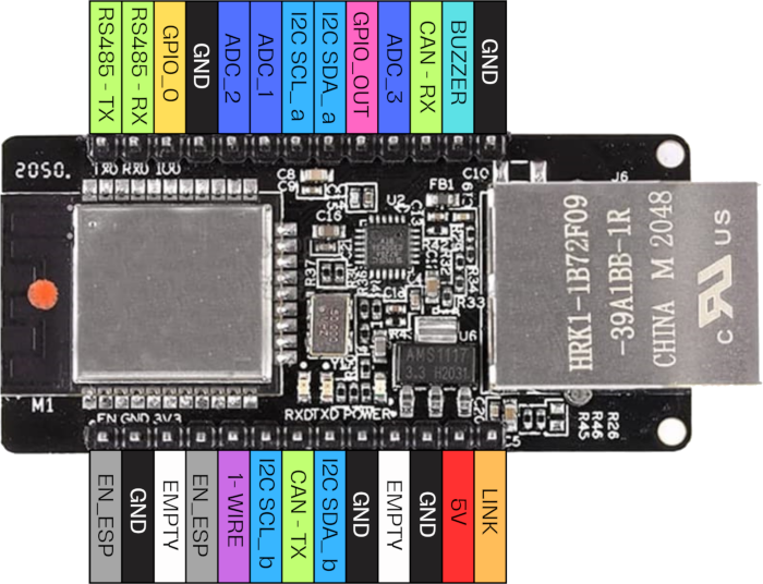
Input Board ESP
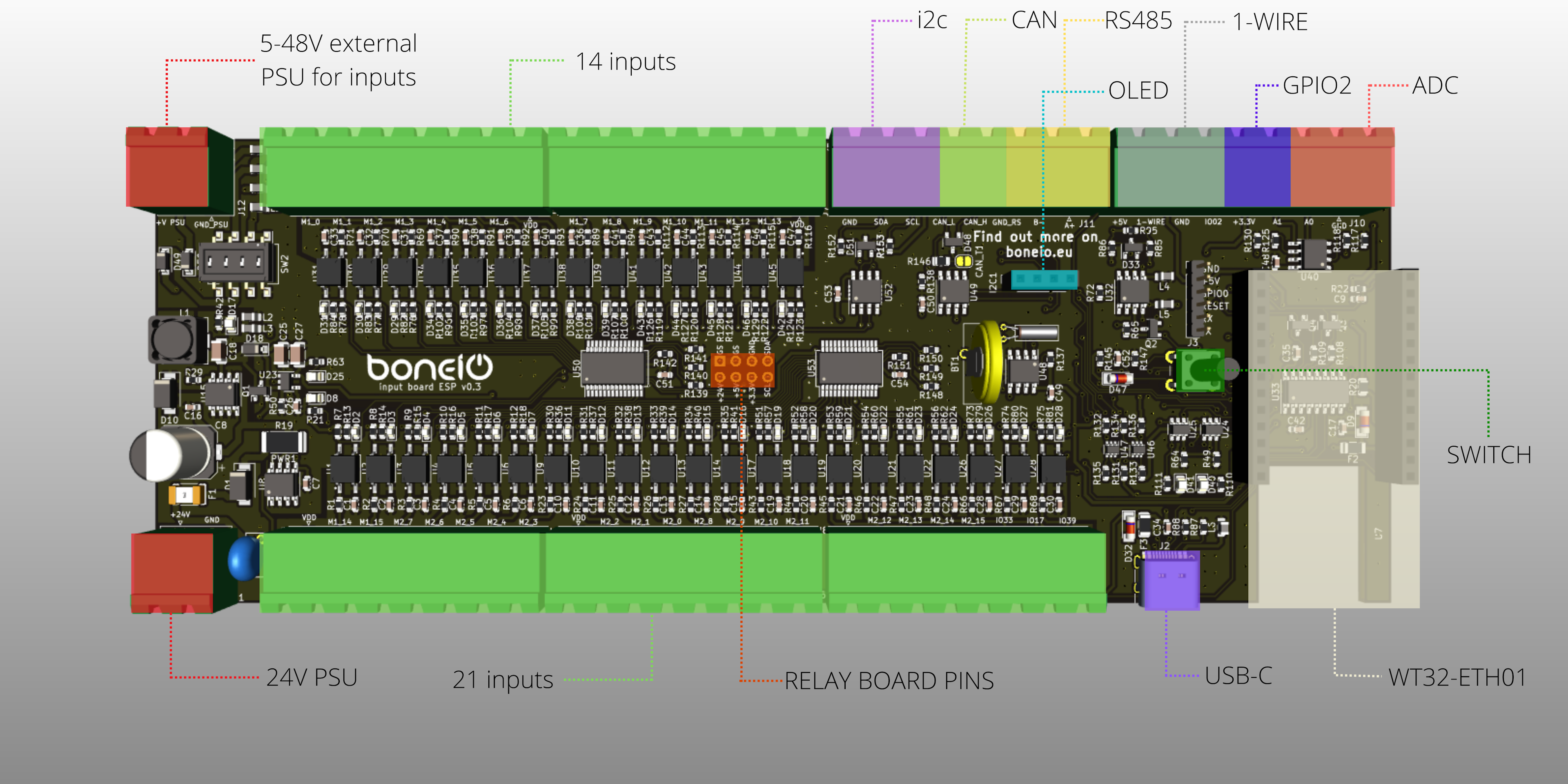
Features
- Power supply 24V DC
- Power supply for controlling inputs with external voltage other than 24V (5V-48V)
- 35 inputs controlled by 24V DC (possibility of connecting switches, detectors, reed switches)
- Outputs (number depends on the Relay Board used)
- I2C bus (expandable with an expansion module or various types of sensors)
- 1-WIRE bus (DS18b20 temperature sensors can be connected)
- CAN bus
- RS485
- GPIO2 ESP connector (direct lead)
- 2 ADC
- Clock RTC
- Ethernet 10/100Mbps
- USB-C (port designed for software uploads)
- 1.3” OLED display
- Button MENU
Repository
Everything about this board you will find here: https://github.com/boneIO-eu/input_board_ESP
Appearance
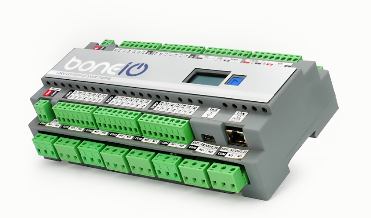
The boneio ESP controller has a housing printed on a 3D printer, the material it was printed from is PET-G. Descriptions for the case available for printing were also designed, as well as the front of the case made of brushed aluminum printed with the LOGO of our product. The descriptions are available here:
Documentation & Schematics
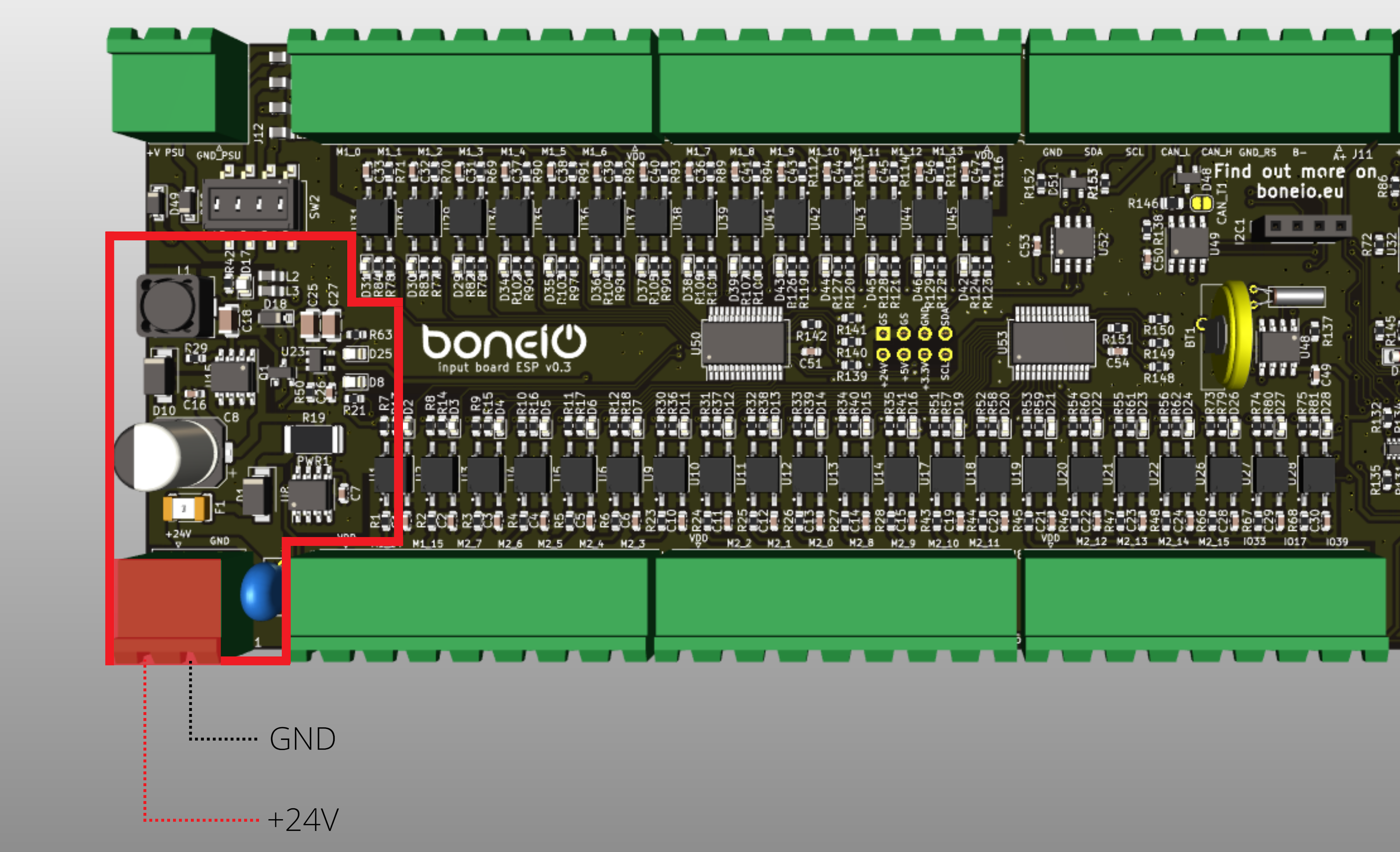
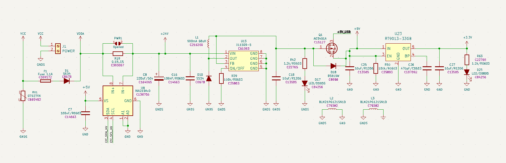
Power Supply
Description of the Power Supply
The circuit is powered by 24V DC from the left side of the connector is supplied +24v, and the right side is GND. At the input of the power supply there is a 1A fuse protection. Then it finds the INA219 circuit, which is responsible for controlling the current measurement of the device. The circuit uses an XL1509-5 inverter, which converts the voltage from +24V to +5V. The +5V voltage is then protected by a mosfet transistor from backfeeding and powering the USB-C port. The +5V is used to power the circuits further mentioned in the documentation, as well as the 3.3v LDO circuit.
INA219
The INA219 is a comprehensive power monitoring solution that measures with 1% accuracy and communicates digitally with the host via an I2C interface. It is capable of measuring current and voltage on the high-voltage side up to 26 V and 3.2 A. A precision current amplifier measures the voltage through a 0.1-ohm, 1% detection resistor (shunt) to determine the current flowing. The combined voltage and current measurements allow power calculation, making the INA219 ideal for tracking boneio module and power measurements.
0x40.Schematic diagram
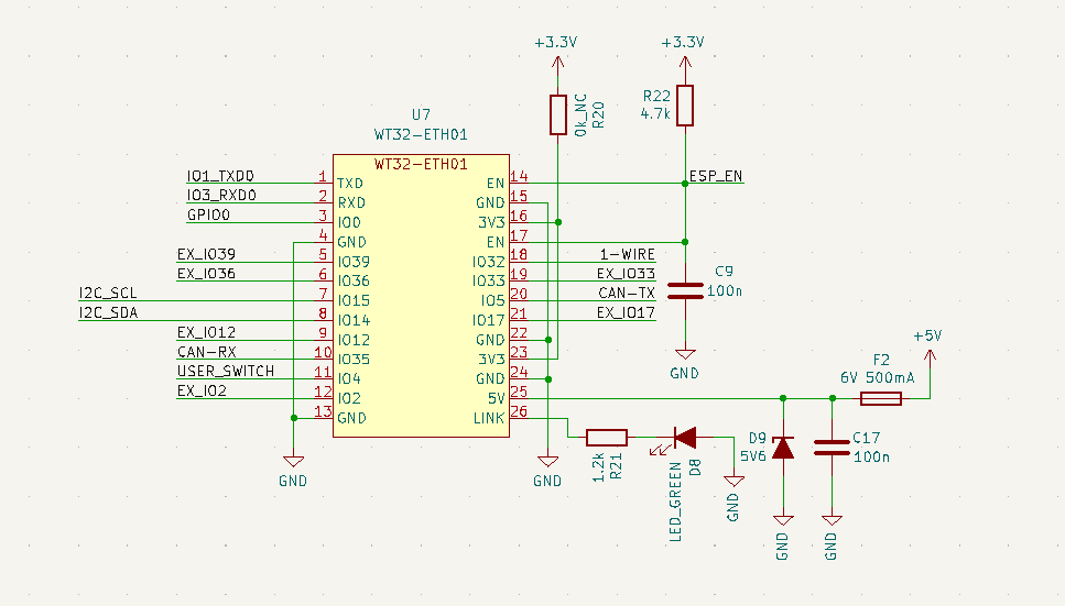
WT32-ETH01
The WT32-ETH01 chip is responsible for the brain in the controller, where the ESP32 is the control processor and the embedded Ethernet, which is controlled by the LAN8720 chip that allows the controller to connect to a LAN. With the LAN connection, the controller communicates via ESPHOME API with a control system such as Home Assistant.
Schematic diagram
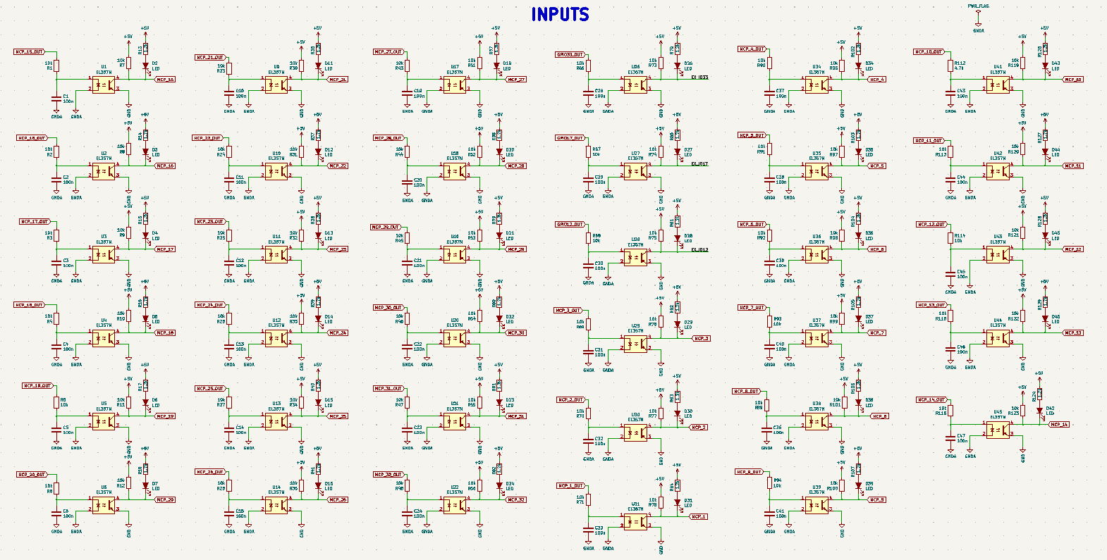
Digital inputs
Description of digital inputs
The operation of digital inputs is based on applying VDD voltage to the IN_1 to IN_35 pin. There is a voltage of +24V on the VDD pin. ESP boneIO module has 35 digital inputs, 32 digital inputs ( IN_1 - IN_32 ) are controlled by two MCP23017 expanders, and the remaining 3 digital inputs ( IN_33 - IN_35 ) come from WT32-ETH01. The GPIOs used from WT32-ETH01 are GPIO33( IN_33) GPIO17 (IN_34) and GPIO12 (IN_35). GPIO12 does not have a pull-up to +5V because it has internally inverted logic.

Schematic diagram
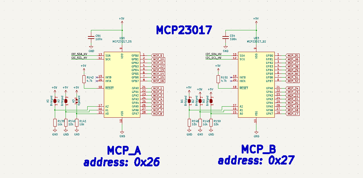
MCP23017 address setting
There are 2 MCP23017-E/SS expanders on the boneio module. The MCP23017-E/SS addresses are set hard, to change them you need to cut a path on the PCB at the location of the placed jumpers. The jumpers are located on the back side of the ESP input board.
MCP23017 on the i2c bus is located at address 0x26 and 0x27 .
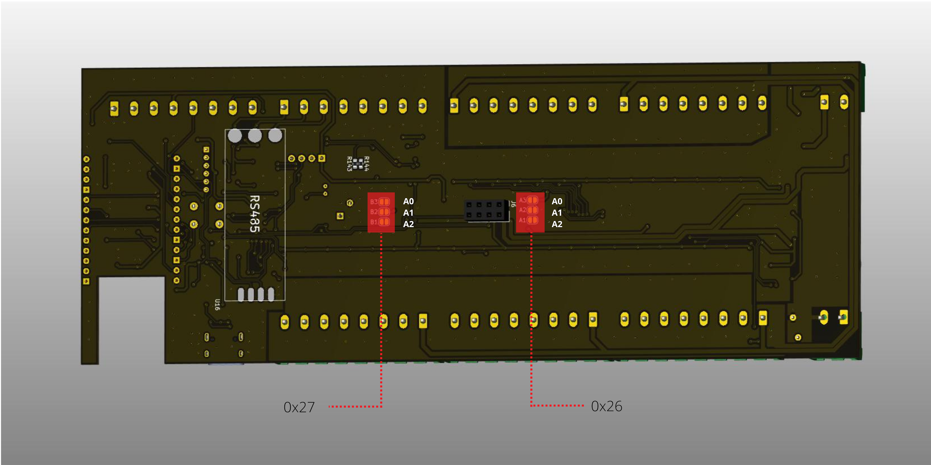
MCP23017 Configuration
| Chip Address | A2 | A1 | A0 | I2C Address |
|---|---|---|---|---|
| 000 | 0x20 | |||
| 001 | Soldered | 0x21 | ||
| 010 | Soldered | 0x22 | ||
| 011 | Soldered | Soldered | 0x23 | |
| 100 | Soldered | 0x24 | ||
| 101 | Soldered | Soldered | 0x25 | |
| 110 | Soldered | Soldered | 0x26 | |
| 111 | Soldered | Soldered | Soldered | 0x27 |
Schematic diagram
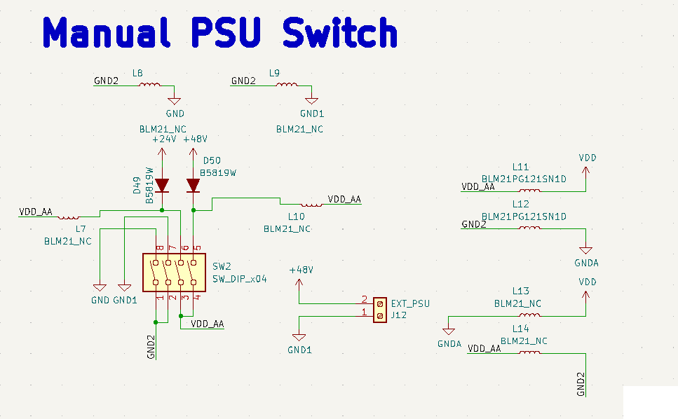
External PSU inputs
Description of launching an external power supply
The input of an external power supply gives the possibility to connect a power supply other than +24v from which the boneIO module is powered, it is possible to connect from +5V to +48V with full galvanic separation. On the PCB there is a dip switch which is used to switch the power supply from +24V which powers the module to an external power supply. The switch is 4 channel. Switching on channels 2 and 4 in the dip switch activates the +24v power supply from the main power supply which powers the entire module, switching on channels 1 and 3 activates the external power supply input.
Note that as channel 2 and 4 are on ON then 1 and 3 must be off and vice versa.

Conversion of digital input control from +24V to GND
By default in the module, the control of digital inputs operates on a +24V supply. It is possible to change the +24V supply to GND. Changing the control to GND requires replacing the EL357N optocouplers with TLP184 and re-soldering the BLM21PG331SN1D from the L11 and L12 positions to L13 and L14.
Schematic diagram
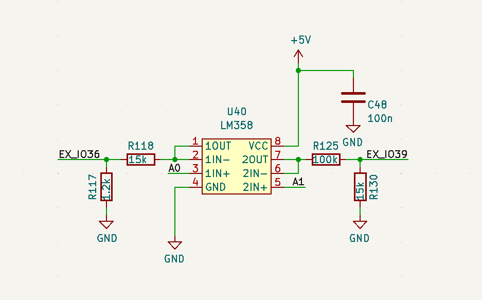
Analog Inputs
2 analog input channels, input power up to 9.9V, equipped with buffer circuit with operational amplifier. Convert the voltage to 0 to 3.3V.
Schematic diagram
USB/CH340C Programmer
The controller uses USB/CH340 to connect to the computer and program the drivers. A mini-USB connector was used for the more modern Type-C, and CH340C as the programmer.
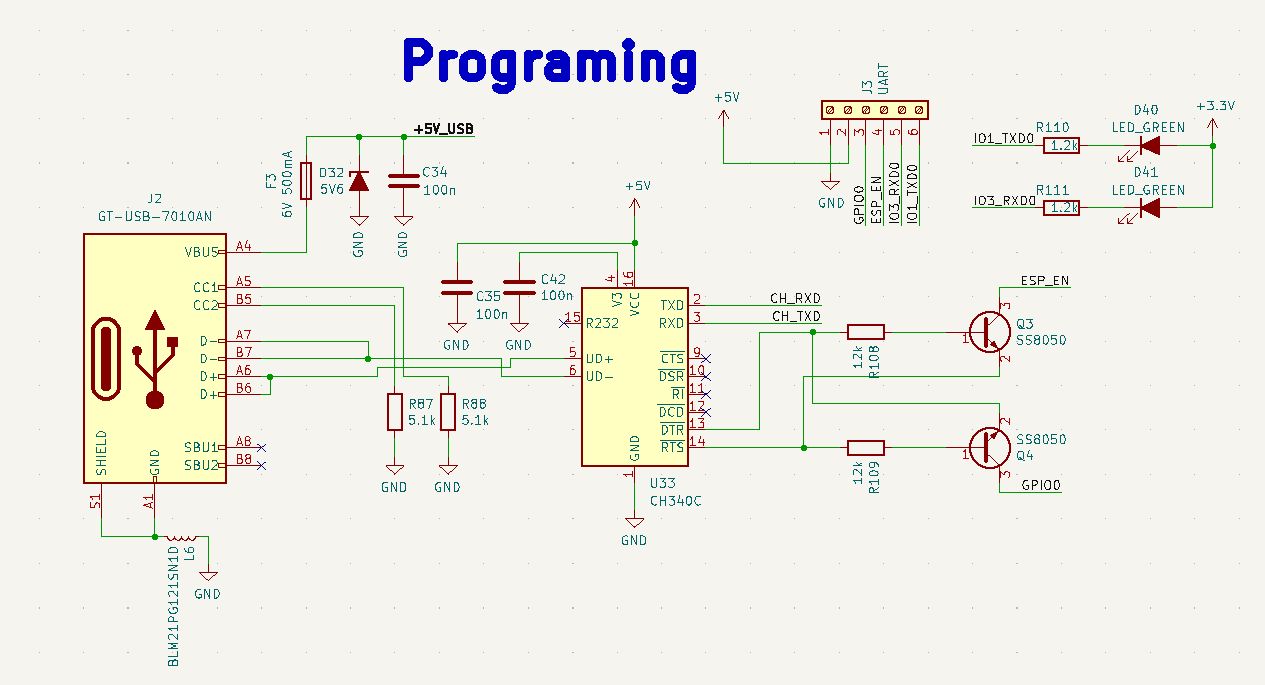
Schematic diagram
Clock RTC
OLED 1.3
Button MENU
CAN bus
RS485
I2C bus
1-WIRE bus
GPIO2 ESP connector (direct lead)
Bill of Materials
| Comment | Designator | Footprint | JLCPBC |
|---|---|---|---|
| 47uH/2.5A | L1 | L_7.3x7.3_H4.5 | C436585 |
| LED_BLUE | D4,LED1,D5 | LED_0603 | C84266 |
| 1234 | Soldered | ||
| 011 | Soldered | Soldered | |
| 100 | Soldered | ||
| 101 | Soldered | Soldered | |
| 110 | Soldered | Soldered | |
| 111 | Soldered | Soldered | Soldered |
Front labels
You can download PDF with front labels from here: