Wiring and Infrastructure
How to properly lay cables in a smart home? Learn the golden rules of cable route separation and wire selection.
The way you lay cables during the shell construction phase will determine your home's capabilities for decades to come. In a boneIO-based installation, we use a star topology. Although it requires more cable than a traditional installation, it's actually simpler to execute and offers incomparably greater flexibility.
What exactly is a "star" installation?
In a traditional electrical installation, cables are run from box to box, creating chains. In the boneIO smart home, we use a star layout. This means that every single point – every button, every roller blind, every lighting circuit – has its own independent cable that runs directly to the central distribution board (the heart of the system).
Why is it important?
- Full flexibility (Software over Hardware): What is a light switch today can become a roller blind button or a "Goodnight" scene trigger tomorrow. Changing the function doesn't require tearing down walls – it is done by changing the configuration in the controller.
- Easy diagnostics: Each cable can be checked directly in the distribution board. If one cable is damaged, the rest of the house operates without disruption.
- Scalability: The distribution board becomes the connection point for all the building's intelligence. Thanks to this, you can easily replace the controller with a newer model in the future without changing the wiring.
Golden Rules for Installation Layout
1. Route Separation and Interference Elimination
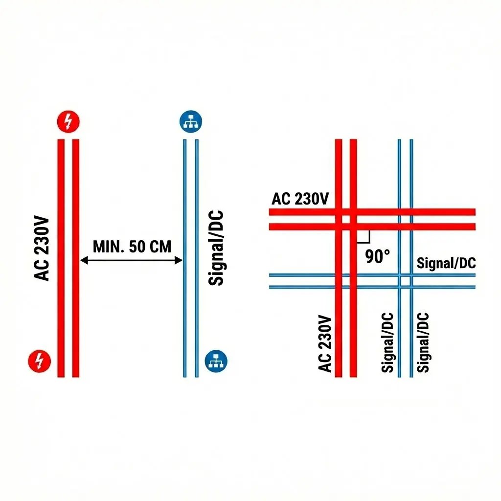
To avoid interference in control signals, it's crucial to physically separate power cables from control cables.
- The 50 cm Rule: Try to maintain at least 50 cm distance between parallel runs of high-voltage cables (230V AC) and signal cables (twisted pairs, buses).
- Right-Angle Crossing: If a control route must cross a power route, always do so at a right angle (90°). Avoid running signal cables parallel at close distances.
- Dedicated Cable Trays: We recommend creating two independent cable routes:
- AC Route: For outlet power, lighting, and high-power devices.
- Control Route: For buttons, sensors, buses (CAN/Modbus), and LAN network.
2. Planning Cabinet Entry
The point where cables converge into the control cabinet is the most critical spot.
- Side Division: Plan routes so that low-voltage signals (DC/twisted pairs) enter the cabinet from one side (e.g., from the top left), and high-voltage cables (AC 230V) from the other. This will prevent cable tangles inside the cabinet and make boneIO controller installation easier.
- Cable Slack: Always leave a minimum of 1.5 - 2 meters of slack for cable coming out of the wall. This allows for aesthetic cable routing in cable ducts and easy termination on terminal blocks. This slack should be placed inside the cabinet or dedicated ducts. It absolutely must not be stuffed into the wall.
Wire Selection – Quality Matters
Saving on cables is the worst decision you can make during construction. The cost of wire relative to the entire investment is small, and replacing it after plastering is impossible.
NEVER USE CCA CABLES!
CCA (Copper-Clad Aluminium) cables are aluminum cables only copper-plated on the outside. They're brittle, have worse conductivity, and oxidize at connections over time. Choose only 100% Cu (copper) cables from reputable manufacturers.
Control and Telecommunications Cables (Star)
All control cables are run in a star topology – from each point (button, sensor) directly to the electrical cabinet.
| Cable Type | Application | Notes |
|---|---|---|
| Cat. 5e FTP Twisted Pair | Buttons, motion sensors, buses | Shielded and copper. Standard for boneIO digital inputs. |
| Cat. 6A / 7 Twisted Pair | LAN network, AP, HA Server | Higher category for reliable network communication and POE cameras. |
| 2x0.5mm Wire | Window reed switches | Easy to install. Note: reed switches with tilt function require 4 wires. |
| Twisted Pair (serial) | Sensor buses | Between temperature sensors, it's worth running twisted pair in series for the CAN bus. |
Power Cables (Loads)
The star principle also applies here: every point you want to control independently must have its own cable running to the electrical cabinet.
- AC Lighting (230V): According to standards, we use minimum 3x1.5mm² cable. Each light point (or group) is run separately to the cabinet.
- Roller Blinds and Shutters: Usually a 4-wire cable (L-up, L-down, N, PE), going directly to boneIO Cover, Cover Mix controllers.
- Controlled Outlets: If you want to measure energy consumption or remotely switch off an outlet (e.g., iron), run a separate 3x2.5mm² cable directly from the cabinet.
DC Lighting Specifics (12V / 24V)
With boneIO Dimmer LED controllers, we need to account for voltage drops:
- Cross-section: For powerful LED strips or long runs, we recommend 2.5mm² cable. In many standard cases, 3x1.5mm² will be sufficient. So if you change concepts at some stage (switching from AC to DC lighting) - 3x1.5mm² cable will handle it.
- Solid vs Stranded: For running through walls, we use solid wire (YDYp). However, for connecting the LED strip in the profile, use stranded wire – it's flexible and won't damage the strip's solder pads.
Bus - Serial Communication.
What is a bus and how is it connected? While most elements are connected in a "star," some devices (e.g., presence sensors or temperature and humidity sensors) communicate via a bus.
Unlike a star, a bus is a shared communication line to which devices "attach" one after another. It can be compared to a road where data goes from device to device.
Why is twisted pair key for the bus?
When connecting a bus (e.g., CAN or RS485), it is essential to use one pair of wires twisted together (e.g., orange and white-orange from a computer network cable).
Why must it be a twisted pair? The bus transmits data using a differential signal. When wires are tightly wrapped around each other (twisted), any external electromagnetic interference affects both wires in the same way. This allows the receiver at the end of the line to easily "cancel out" these interferences and read a clean signal.
Why won't two regular wires work? If you use two wires that are not twisted together (e.g., individual single strands run loosely), they will start acting like an antenna. They will pick up noise from the 230V installation, motors, or power supplies. Without twisting, the interference will be so significant that communication will be interrupted, and devices will stop "seeing" each other or start throwing errors.
How to connect in practice?
- Serial (Daisy-Chain): The only correct way. The cable enters the first device, exits it, and goes to the next. We create one continuous line (chain). In boneIO systems, we take a practical approach – we run the twisted pair from the distribution board to several points (e.g., temperature sensors) in a loop or a single run, which saves space in cable trays while maintaining signal stability.
Advantages of the bus:
- Wiring savings: Instead of pulling 10 cables to 10 temperature sensors, we pull one wire that "visits" them all.
- Standards: boneIO supports, among others, the CAN bus and RS485 (Modbus), allowing integration with thousands of industrial devices, energy meters, or heat pumps.