Overview and Specification
Discover the boneIO ESP Input24 gen2 control unit with 24 digital inputs.
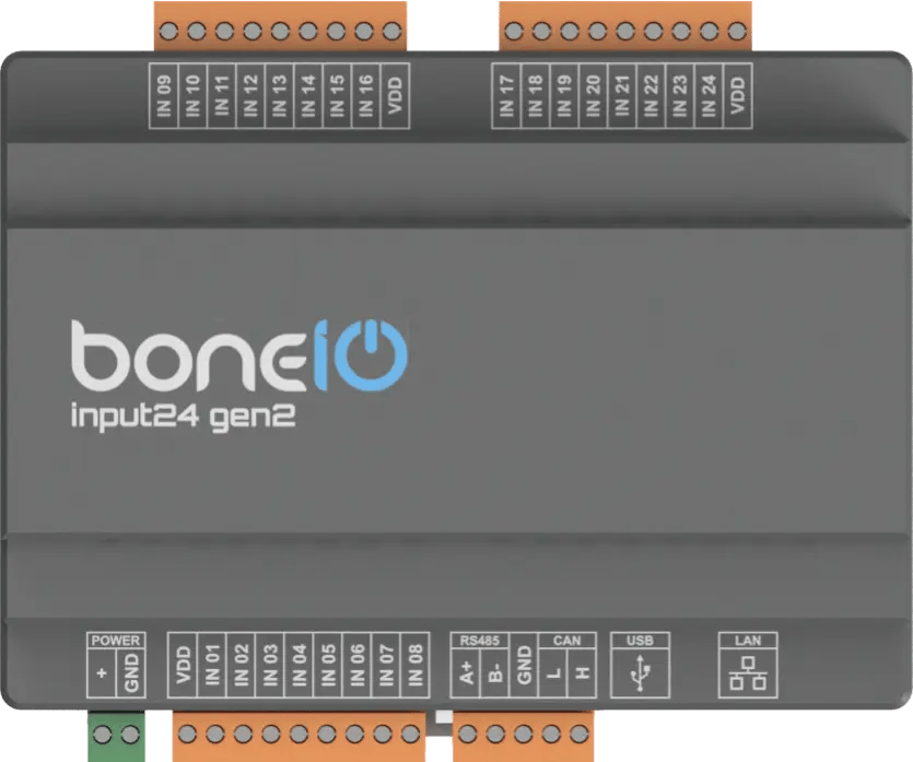
boneIO ESP Input24 gen2
You can buy the controller -> HERE
Leveraging the versatile ESP32-S3 microcontroller and the simplicity of ESPHome, the boneIO ESP Input24 gen2 controller provides an incredibly easy way to expand number of inputs in your Home Automation system.
Thanks to 24 digital inputs placed in an extremely small enclosure - we significantly increase the system's potential. The controller can be used for button control or as a central unit for handling motion sensors and reed switches! The boneIO Input24 was primarily designed as a device to increase the number of inputs supported by the system.
Key Features
- 24 digital inputs For connecting switches, motion sensors, contact sensors and others.
- Reliable network connection via Ethernet and WiFi (with external antenna).
- Wide expansion capabilities thanks to Modbus, and CAN interfaces.
- USB-C port for easy firmware installation.
- Compact 7-module DIN rail enclosure.
Use Cases
The boneIO ESP Input24 gen2 controller is the perfect choice for:
- Integration with an alarm system by collecting signals from sensors.
- Integration with various sensors for advanced automation scenarios.
- Automating HVAC systems (heating, ventilation, air conditioning) thanks to Modbus support.
Technical Specification
| Feature | Value |
|---|---|
| Module | ESP32-S3 |
| Power Supply | 12-24V DC |
| Power Consumption | Max. 7W |
| Digital Inputs | 24 |
| External Interfaces | Modbus RS485, CAN |
| Communication | Ethernet 10/100Mbit, Wi-Fi (with external antenna), USB-C (for firmware) |
| Dimensions (WxHxD) | 126mm x 91mm x 57mm (without plugs) / 126mm x 108mm x 57mm (with plugs) |
| Mounting Width | 7 DIN modules |
| Weight | 230g |
Connectors and Components Description
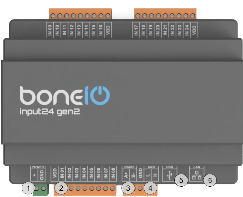
- Power Connector (VCC/GND): Main device power supply (12-24V DC).
- IN (1-8) Screw Terminals: Digital inputs for buttons or sensors.
- Modbus RS485 Connector: Modbus connector for connecting Modbus devices.
- CAN Bus Connector: CAN connector for connecting CAN devices.
- USB-C Connector: For uploading firmware.
- Ethernet Port (RJ45): For connecting to the LAN.
Quick Start Guide
- Device Installation: A qualified person must mount the device on a DIN rail.
- Connect input: Connect a switch to input IN01. Press the switch – the input should change its state.
- Network Connection: Plug a LAN cable into the RJ45 port.
- Accessing the Web Panel: Find the device's IP address (displayed on the OLED screen or in your router) and enter it into a browser to access the web interface.
Certificates
What's Next?
You can find detailed instructions on the dedicated pages. Go ahead and read it!