Hardware Installation
A detailed guide to wiring the boneIO ESP Input24 gen2 controller.
Key Safety Principals
IMPORTANT: PROFESSIONAL INSTALLATION REQUIRED
We emphasize in the strongest possible terms: safety is the absolute priority. All activities related to connecting the device to an electrical installation must be performed exclusively by a qualified electrician who holds the appropriate certifications. Installation by unqualified individuals poses a risk of electric shock, equipment damage, or fire. The manufacturer assumes no liability for damages resulting from an improper installation.
This applies in particular to:
- Connecting the power supply to the controller.
- Connecting high-voltage circuits (110V/230V) to the controller's outputs.
- All installation work inside the electrical cabinet (distribution board).
Attempting to modify an electrical installation without the proper qualifications is illegal, extremely dangerous, and creates a real hazard that can lead to:
- Electric shock, severe personal injury, or death.
- Permanent damage to the boneIO controller and all connected equipment.
- A significant fire hazard resulting in property damage.
- Voiding the product warranty and potential issues with property insurance claims.
The manufacturer of boneIO assumes no liability whatsoever for material damages, personal injury, or loss of life resulting from an installation performed contrary to these guidelines and applicable safety standards.
Please treat this warning with the utmost seriousness.
DIN Rail Mounting
The boneIO ESP controller is designed for mounting on a standard DIN rail (TS35).
- Hook the upper clips of the enclosure onto the top edge of the DIN rail.
- Press the lower part of the enclosure firmly until the latches lock onto the rail with a distinct click.
- Ensure the module is securely mounted.
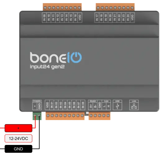
Power Supply Connection
The device requires a stabilized 12-24V DC power supply.
- Ensure the power supply is disconnected from the 230V/110V mains.
- Connect the
+output of the power supply to the+screw terminal on the boneIO. - Connect the
GND(ground) output of the power supply to theGNDscrew terminal on the boneIO. - Double-check the connections and polarity before turning on the power supply.
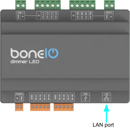
Connect Ethernet
The device communicates with the network using a built-in Ethernet port, which guarantees a stable and reliable connection. To establish connectivity, connect the module to your network switch using a standard Ethernet (RJ45) cable.
- Connect ethernet cable to LAN port on your controller.
- Connect other side of ethernet cable to your network switch.
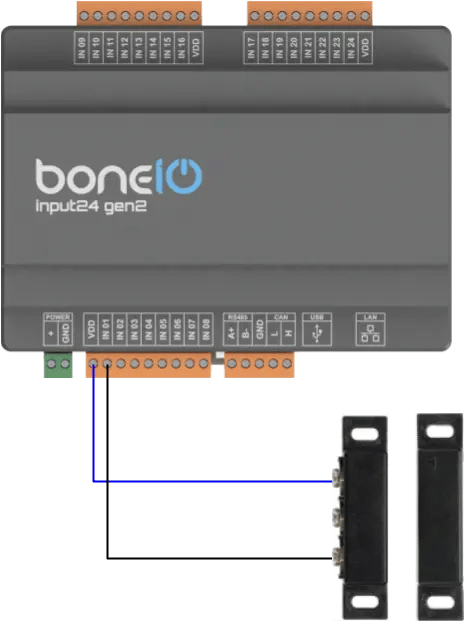
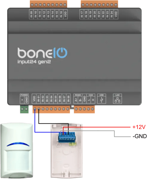
Connecting Digital Inputs
Digital inputs are used for connecting switches and sensors. By default, they are ground-controlled.
- Connect one of the wires from a momentary switch to the common
GND(ground) terminal. - Connect the other wire to the desired input terminal (e.g.,
IN01). - Pressing the switch will short the input to ground, which will be interpreted as an "on" signal.
Logical diagram of connecting digital input
GND or +
Input behavior can be changed via the internal switch. Please see the switch location below.
- Down: GND control.
- Up: High-potential control.
Example:
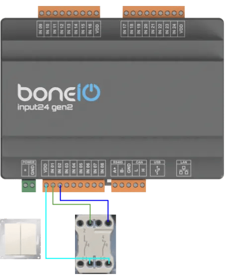
Example 2:
Example 3:
Connecting Communication Buses
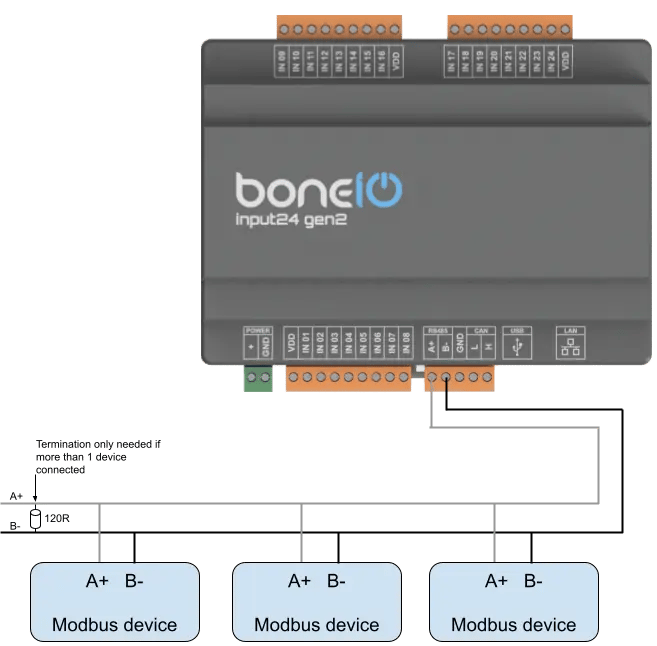
Modbus RS485
Used for communication with industrial and HVAC devices.
- Connect the
Aline of the bus to theAterminal on the boneIO. - Connect the
Bline of the bus to theBterminal on the boneIO.
ESP series devices have undergone Modbus RTU bus testing with 5 connected devices. Using a larger number of Modbus devices connected to an ESP series controller may cause delays in the controller's response (both inputs and outputs). This is due to the specifics of the processor used. In the case of extensive Modbus buses, we recommend splitting them across several devices.
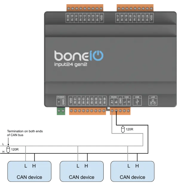
CAN
Used for communication with industrial HVAC devices and sensors.
- Connect the
Lline of the bus to theLterminal on the boneIO. - Connect the
Hline of the bus to theHterminal on the boneIO.
Final Checks
After completing the installation:
- Double-check all connections.
- Ensure there are no short circuits.
- Turn on the main power (24V DC power supply).