Overview and Specification
Discover the boneIO ESP Dimmer gen2, an 8-channel PWM controller for advanced LED lighting automation.
boneIO ESP Dimmer gen2
You can buy the controller -> HERE
The boneIO ESP Dimmer gen2 is a professional 8-channel PWM controller designed for automating LED lighting. It allows for precise control over single-color, RGB, or RGBW LED strips, enabling the creation of advanced lighting scenes. The device is divided into two sections, each with 4 channels, and is equipped with digital inputs for connecting wall switches.
Key Features
- 8 digital inputs for connecting momentary switches or sensors.
- 8 PWM output channels organized in two sections of 4 channels.
- High current capacity: up to 10A per channel and 10A per section.
- Reliable network connection via Ethernet and WiFi (with external antenna).
- Wide expansion capabilities thanks to Modbus, and CAN interfaces.
- USB-C port for easy firmware installation.
- Compact 7-module DIN rail enclosure.
Use Cases
- Advanced control of single-color or multi-color (RGB/RGBW) LED strips.
- Creating dynamic lighting scenes and animations.
- Integrating LED lighting with a smart home system.
- Manual control of lighting using traditional wall switches.
- Automating HVAC systems (heating, ventilation, air conditioning) thanks to Modbus and CAN support.
Technical Specification
| Feature | Value |
|---|---|
| Module | ESP32-S3 |
| Power Supply | 12-24V DC |
| Power Consumption | Max. 7W (excluding LED strip consumption) |
| Digital Inputs | 8 |
| PWM Channels | 8 (2 sections x 4 channels) |
| Max Output Voltage | 24V DC |
| Max Output Current | 10A per channel / 10A per section |
| PWM Frequency | 10Hz – 40MHz |
| External Interfaces | Modbus RS485, CAN |
| Communication | Ethernet 10/100Mbit, Wi-Fi (with external antenna), USB-C (for firmware) |
| Dimensions (WxHxD) | 126mm x 91mm x 57mm (without plugs) / 126mm x 108mm x 57mm (with plugs) |
| Mounting Width | 7 DIN modules |
| Weight | 230g |
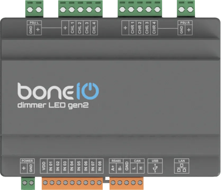
Connectors and Components Description
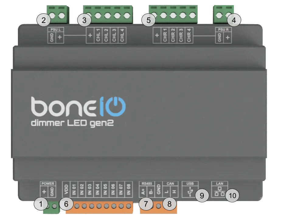
- Power Connector (VCC/GND): Main device power supply (12-24V DC).
- Power Connector for Section L: Power supply connection.
- Output Channel Screw Terminals - CHL1-CHL4: PWM outputs for connecting LED strips.
- Power Connector for Section R: Power supply connection.
- Output Channel Screw Terminals - CHR1-CHR4: PWM outputs for connecting LED strips.
- IN (1-8) Screw Terminals: Digital inputs for buttons or sensors.
- Modbus RS485 Connector: Modbus connector for connecting Modbus devices.
- CAN Bus Connector: CAN connector for connecting CAN devices.
- USB-C Connector: For uploading firmware.
- Ethernet Port (RJ45): For connecting to the LAN.
NEVER CONNECT THE USB-C PORT WITH THE POWER SUPPLY CONNECTED!!!
The USB-C port is dedicated to flashing firmware. This should be done ONLY with the controller's power supply disconnected. Using the USB-C port with the power connector plugged in risks DAMAGING the controller!
Quick Start Guide
- Device Installation: Mount the device on a DIN rail and connect the 12-24V DC power supply.
- Connect LED Strips: Connect your LED strips to the PWM output channels.
- Connect Switches: Connect momentary switches to the digital inputs for manual control.
- Network Connection: Plug a LAN cable into the RJ45 port or configure Wi-Fi.
- Accessing the Web Panel: Find the device's IP address and enter it into a browser to access the web interface.