Hardware Installation
Detailed instructions and wiring diagrams for the boneIO Black Cover controller, including power, inputs, outputs, and communication buses.
Key Safety Principals
IMPORTANT: PROFESSIONAL INSTALLATION REQUIRED
We emphasize in the strongest possible terms: safety is the absolute priority. All activities related to connecting the device to an electrical installation must be performed exclusively by a qualified electrician who holds the appropriate certifications. Installation by unqualified individuals poses a risk of electric shock, equipment damage, or fire. The manufacturer assumes no liability for damages resulting from an improper installation.
This applies in particular to:
- Connecting the power supply to the controller.
- Connecting high-voltage circuits (110V/230V) to the controller's outputs.
- All installation work inside the electrical cabinet (distribution board).
Attempting to modify an electrical installation without the proper qualifications is illegal, extremely dangerous, and creates a real hazard that can lead to:
- Electric shock, severe personal injury, or death.
- Permanent damage to the boneIO controller and all connected equipment.
- A significant fire hazard resulting in property damage.
- Voiding the product warranty and potential issues with property insurance claims.
The manufacturer of boneIO assumes no liability whatsoever for material damages, personal injury, or loss of life resulting from an installation performed contrary to these guidelines and applicable safety standards.
Please treat this warning with the utmost seriousness.
DIN Rail Mounting
The boneIO ESP controller is designed for mounting on a standard DIN rail (TS35).
- Hook the upper clips of the enclosure onto the top edge of the DIN rail.
- Press the lower part of the enclosure firmly until the latches lock onto the rail with a distinct click.
- Ensure the module is securely mounted.
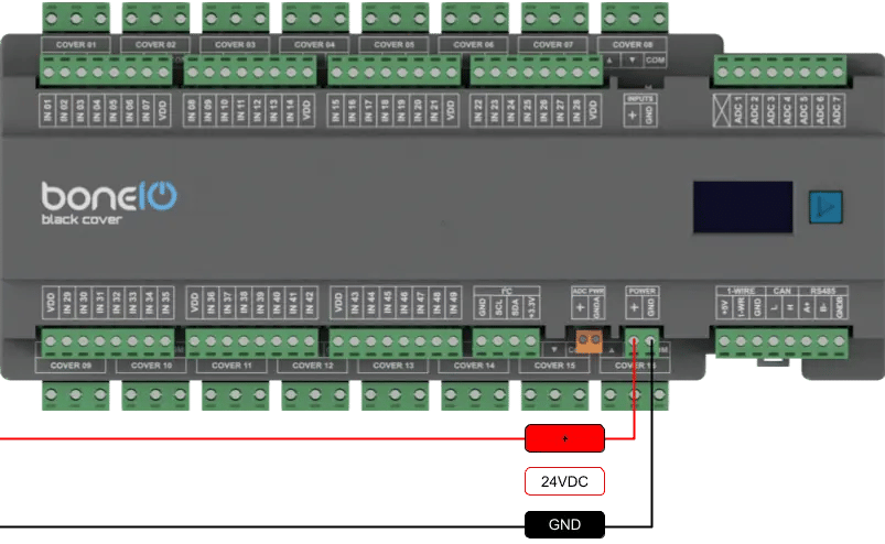
Power Supply Connection
The device requires a stabilized 24V DC power supply.
- Ensure the power supply is disconnected from the 230V/110V mains.
- Connect the
+24Voutput of the power supply to the+screw terminal on the boneIO. - Connect the
GND(ground) output of the power supply to theGNDscrew terminal on the boneIO. - Double-check the connections and polarity before turning on the power supply.
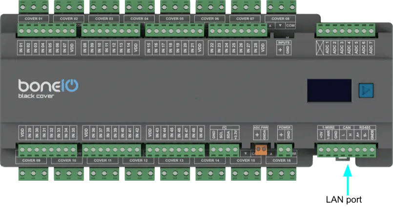
Connect Ethernet
The device communicates with the network using a built-in Ethernet port, which guarantees a stable and reliable connection. To establish connectivity, connect the module to your network switch using a standard Ethernet (RJ45) cable.
- Connect ethernet cable to LAN port on your controller.
- Connect other side of ethernet cable to your network switch.
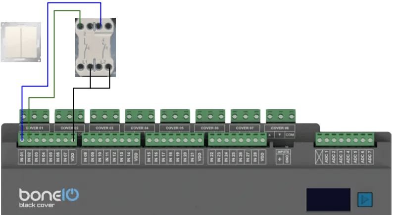
Connecting Digital Inputs
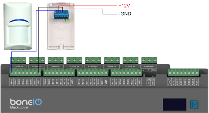
Digital inputs are used to connect buttons and sensors. To change the potential used to control the inputs, use the switch on the casing marked INPUTS. By default, the inputs are controlled by ground (GND).
IMPORTANT: If you want to change the position of the switch - make sure you do it while the device is turned off!
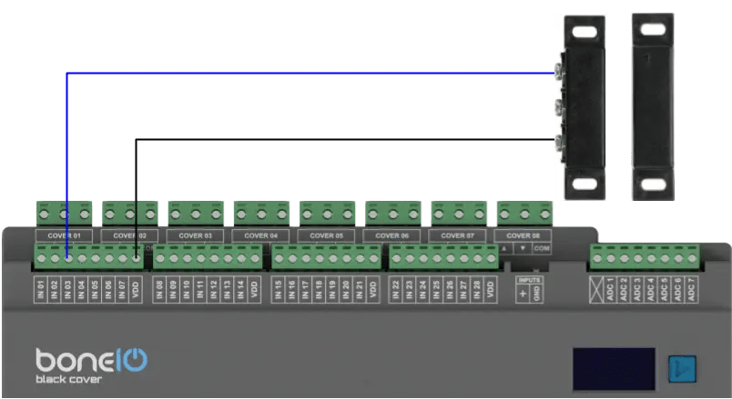
- Connect one of the wires from a momentary switch to the common
GND(ground) terminal. - Connect the other wire to the desired input terminal (e.g.,
IN01). - Pressing the switch will short the input to ground, which will be interpreted as an "on" signal.
Logical diagram of connecting digital input
Example:
Example 2:
Example 3:
Connecting Relay Outputs (Cover Motors)
The key feature of the Cover version is that it has 32 relays, which are paired to control up to 16 roller shutter motors. Each pair of relays (e.g., Cover 01UP/DOWN, Cover 02 UP/DOWN) is protected by a hardware interlock to prevent simultaneous 'up' and 'down' signals, which protects the motor from damage.
Protection and Correct Wiring Order
It is critical that all overcurrent protection (Miniature Circuit Breakers, MCBs) and residual-current devices (RCDs) are installed in the circuit before the boneIO controller.
The current rating (in Amps) of the overcurrent protection must be sized appropriately for the planned load of the circuit (in this case - cover motors), but at the same time, it must not exceed the maximum rated current of the relay, which is 10A.
The correct current flow for the phase (L) wire is as follows:
RCD Protection -> Overcurrent Protection (MCB) -> COM terminal in boneIO -> UP/DOWN terminal in boneIO -> COVER
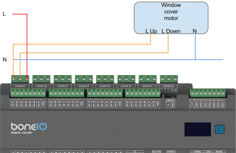
Example 1: Controlling a standard cover circuit
- Connect the phase wire (L), coming from the dedicated overcurrent protection (MCB ≤ 10A), to the
COMterminal of the selected Cover output (e.g.,Cover 01 COM). - Connect the wire leading to the Cover motor UP to the
UPterminal of the same output (e.g.,Cover 01 UP). - Connect the wire leading to the Cover motor DOWN to the
DOWNterminal of the same output (e.g.,Cover 01 DOWN). - Run the neutral wire (N) directly to the load (cover engine).
Logical Diagram
Safe Connecting of COM and OUT Terminals
In the boneIO controller, version Cover every two outputs (e.g., Cover 01 UP and DOWN) share a single common power terminal COM. This means that the phase wire (L) from a single circuit breaker supplies a pair of relays - with hardware interlock.
- REMEMBER, ensure that the relevant circuit breakers in the electrical cabinet are turned off.
- Connect the phase wire (L), coming from the overcurrent protection, to the appropriate COM terminal - tighten it with adequate force.
- Connect the wire leading to your load (e.g., a cover motor) to its corresponding output terminal - tighten it with adequate force.
- Run the neutral (N) wire directly from the neutral bar to the load.
Connecting Communication Buses
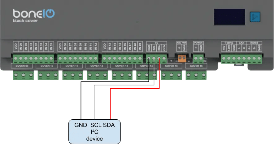
I2C Bus
For connecting additional sensors and expanders over short distances.
- Connect the
SDAline to theSDAterminal. - Connect the
SCLline to theSCLterminal. - Also, connect the
VCCandGNDpower for the sensor.
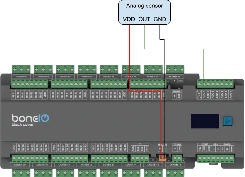
Analog Inputs ADC
Analog inputs allow you to read values from sensors that do not operate in a binary (on/off) manner.
The boneIO Black controller is equipped with 7 analog inputs. The maximum voltage that can be applied to an analog input is 1.8V. To enable measurement from sensors with a higher voltage, an external voltage divider must be used.
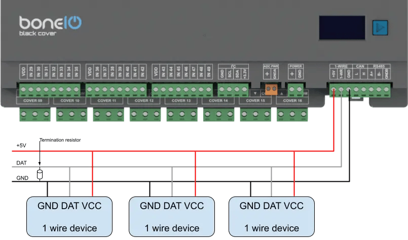
1-Wire Bus
Popular for connecting temperature sensors (e.g., DS18B20).
- Connect the
DATAline to the1-Wireterminal. - Also, connect
VCCandGNDpower.
The maximum length of the bus cable is 20m.
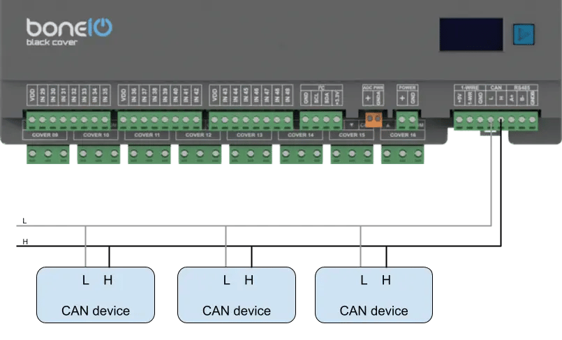
CAN
Used for communication with industrial HVAC devices and sensors.
- Connect the
Lline of the bus to theLterminal on the boneIO. - Connect the
Hline of the bus to theHterminal on the boneIO.
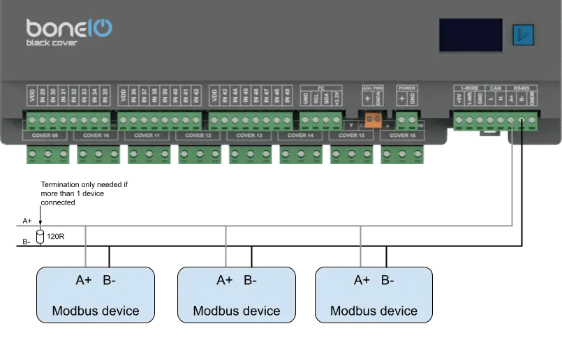
Modbus RS485
Used for communication with industrial and HVAC devices.
- Connect the
Aline of the bus to theAterminal on the boneIO. - Connect the
Bline of the bus to theBterminal on the boneIO.