Overview and Specification
Discover the boneIO ESP Cover Mix, a hybrid controller with 8 cover outputs and 16 relay outputs for complete home automation.
boneIO ESP Cover Mix
You can buy the controller -> HERE
Utilizing the versatile ESP32 microcontroller and the simplicity of ESPHome software, the boneIO ESP controller provides an extremely flexible and easy-to-configure core for your smart home automation. With 35 digital inputs, 8 roller blind outputs, and 16 relay outputs, a single unit has enough power to manage all the automation in a house or apartment. This includes lighting and heating systems, as well as controlling entrance and garage gates by providing a pulse to the drive. It is also possible to control roller blinds thanks to dedicated outputs. boneIO ESP Cover Mix is a versatile controller that combines the features of a standard relay module with a specialized roller blind controller. It features 32 relays, 16 of which are paired with a hardware interlock to control up to 8 bidirectional motors (e.g., roller blinds), while the remaining 16 relays can be used for general purposes, such as controlling lighting circuits.
Key Features
- 35 digital inputs for connecting switches, motion sensors, contact sensors and others.
- Hybrid Outputs: 32 relays in total, including 8 pairs with a hardware interlock (motor protection) for controlling 8 roller shutters and 16 individual relays (10A) for general use.
- 3 analog inputs for integration with analog sensors (e.g., light or wind sensors).
- Reliable network connection via an Ethernet port and USB-C.
- Wide expansion capabilities thanks to Modbus, I2C, CAN and 1-Wire interfaces.
- Built-in OLED screen for a quick overview of the device's status.
- Standard DIN Rail Mounting (12 modules).
Use Cases
The boneIO Cover Mix model is perfect choice for:
- Comprehensive automation of roller shutters and lighting in single-family homes and large apartments.
- Creating advanced scenes combining shutter control and lighting.
- Integration with an alarm system to automatically close all shutters when the alarm is armed.
- Integration with various sensors for advanced automation scenarios.
- Automating HVAC systems (heating, ventilation, air conditioning) thanks to Modbus support.
Technical Specification
| Feature | Value |
|---|---|
| Module | ESP32 |
| Power Supply | 24V DC |
| Power Consumption | 3W - 15W |
| Digital Inputs | 35 |
| Inputs Voltage | 24V DC |
| Relay Outputs | 32 (16 general purpose + 8 pairs with hardware interlock) |
| Max Output Voltage | 230V AC / 30V DC |
| Max Output Current | 10A |
| Analog Inputs | 3 (A_1 - 0-5V, A_2 - 0-10V, A_3 0-25V) |
| External Interfaces | Modbus RS485, I2C bus, 1-Wire, CAN (for future use) |
| Communication | Ethernet 10/100Mbit, USB-C (for firmware installation) |
| Dimensions (WxHxD) | 216mm x 106mm x 57mm (without plugs) / 216mm x 123mm x 57mm (with plugs) |
| Mounting Width | 12 DIN modules |
| Weight | 800g |
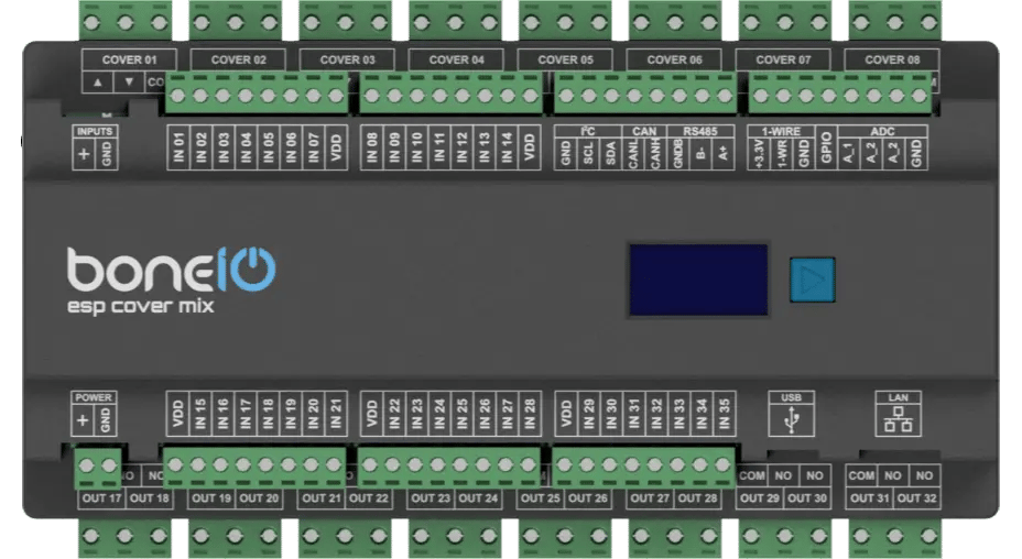
Connectors and Components Description
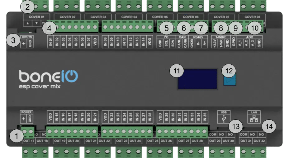
- Power Supply Connector (VCC/GND): Main power supply for the device (24V DC).
- OUT Screw Terminals: Top part Cover Up/Down (for cover 1-8) lower part Relay outputs 17-32.
- Inputs control switch: Inputs can be controlled either by + or GND.
- IN Screw Terminals (1-35): Digital inputs.
- I²C bus connector: For connecting I²C devices.
- CAN bus connector: For connecting CAN devices. For future use.
- Modbus RS485 connector: For connecting Modbus devices.
- 1-Wire bus connector: For connecting 1-Wire devices.
- GPIO connector: For connecting devices that can transmit data to ESP32 GPIO. It's pulled down to GND.
- ADC connector: For connecting analog sensors to get an analog reading of voltage.
- OLED Screen: Displays key information about the device's status.
- Control Button: Used to switch between different views on the OLED display.
- USB-C connector: For connecting to a computer to upload the firmware.
- Ethernet Port (RJ45): For connecting to the LAN.
Quick Start Guide
- Device Installation: A qualified person must mount the device on a DIN rail.
- Network Connection: Plug a LAN cable into the RJ45 port.
- Accessing the Web Panel: Find the device's IP address (displayed on the OLED screen or in your router) and enter it into a browser to access the web interface.
- Estimate Shutter Movement Time: Measure the time it takes for the shutter to fully open or close.
- Connect the Shutter: Turn off the shutter's circuit breaker. Connect the shutter motor to the
Cover01 Up/Downoutputs. - Compile and Upload Firmware: Set the estimated movement time in the configuration and upload the new firmware.
- Test the Shutter: Run the shutter from the web panel to verify the configuration.
Certificates
What's Next?
You can find detailed instructions on the following pages:
- Hardware Installation: Detailed wiring diagrams.
- Software Setup: A step-by-step guide to configure your device.