Overview and Specification
Discover the boneIO ESP central control unit with 35 digital inputs and 32 relay outputs, perfect for whole-home automation.
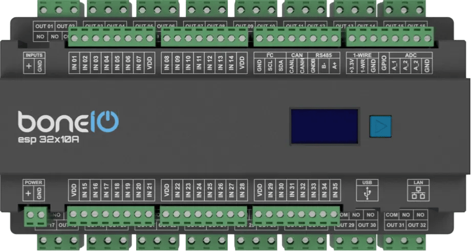
boneIO ESP 32x10A
You can buy the controller -> HERE
Leveraging the versatile ESP32 microcontroller and the simplicity of ESPHome, the boneIO ESP controller provides an incredibly flexible and easy-to-configure core for your smart home automations. With 35 digital inputs and 32 relay outputs, a single boneIO ESP controller has enough capacity to manage all the automation in an entire house or apartment. This includes lighting and heating systems, as well as controlling entrance and garage gates by providing a pulse to the drive. It's also possible to control blinds (though we offer dedicated controllers for this purpose). The boneIO ESP 32x10A is designed to manage lights and some other not electrical demanding devices throughout your home.
Key Features
- 35 digital inputs For connecting switches, motion sensors, contact sensors and others.
- 32 relay outputs (10A) For controlling lights, outlets, valves.
- 3 analog inputs for integration with analog sensors (e.g., light or wind sensors).
- Reliable network connection via an Ethernet port and USB-C.
- Wide expansion capabilities thanks to Modbus, I2C, CAN and 1-Wire interfaces.
- Built-in OLED screen for a quick overview of the device's status.
- Standard DIN rail mounting (12 modules).
Use Cases
The boneIO controller is the perfect choice for:
- Comprehensive automation of single-family homes and large apartments.
- Controlling multiple lighting circuits from a single location.
- Integration with an alarm system by collecting signals from sensors.
- Integration with various sensors for advanced automation scenarios.
- Automating HVAC systems (heating, ventilation, air conditioning) thanks to Modbus support.
Technical Specification
| Feature | Value |
|---|---|
| Module | ESP32 |
| Power Supply | 24V DC |
| Power Consumption | 3W - 15W |
| Digital Inputs | 35 |
| Inputs Voltage | 24V DC |
| Relay Outputs | 32 |
| Max Output Voltage | 230V AC / 30V DC |
| Max Output Current | 10A |
| Analog Inputs | 3 (A_1 - 0-5V, A_2 - 0-10V, A_3 0-25V) |
| External Interfaces | Modbus RS485, I2C bus, 1-Wire, CAN (for future use) |
| Communication | Ethernet 10/100Mbit, USB-C (for firmware installation) |
| Dimensions (WxHxD) | 216mm x 106mm x 57mm (without plugs) / 216mm x 123mm x 57mm (with plugs) |
| Mounting Width | 12 DIN modules |
| Weight | 800g |
Connectors and Components Description
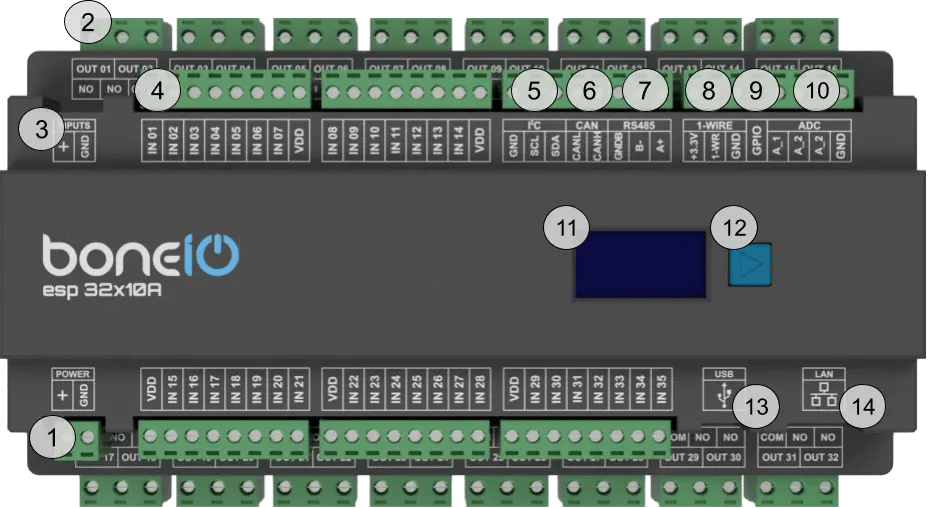
- Power Supply Connector (+/GND): Main power supply for the device (24V DC).
- OUT Screw Terminals (1-32): Relay outputs.
- Inputs control switch - inputs can be controlled either by + or GND.
- IN Screw Terminals (1-35): Digital inputs.
- I²C bus connector: I²C bus connector for connecting I²C devices.
- CAN bus connector: CAN bus connector for connecting CAN devices. For future use.
- Modbus RS485 connector: Modbus RS485 connector for connecting Modbus devices.
- 1-Wire bus connector: 1-Wire bus connector for connecting 1-Wire devices.
- GPIO connector: GPIO connector for connecting device which can transmit data to ESP32 GPIO. It's pulled down to GND.
- ADC connector: ADC connector for connecting analog sensors to get analog reading of voltage.
- OLED Screen: Displays key information about the device's status, such as IP address, connection status, or CPU load.
- Control Button: Located next to the screen, it is used to switch between different views on the OLED display.
- USB-C connector: USB-C connector for connecting to the computer to upload the firmware.
- Ethernet Port (RJ45): For connecting to the LAN.
Quick Start Guide
- Device Installation: A qualified person must mount the device on a DIN rail.
- Offline Verification: Connect a switch to input IN01 and a light bulb to output OUT01. Press the switch – the bulb should change its state.
- Network Connection: Plug a LAN cable into the RJ45 port.
- Accessing the Web Panel: Find the device's IP address (displayed on the OLED screen or in your router) and enter it into a browser to access the web interface.
Certificates
What's Next?
You can find detailed instructions on the dedicated pages. Go ahead and read it!