Overview and Specification
Discover the boneIO ESP 24x16A controller with 24 independent 16A relays, designed for controlling high-power circuits like outlets or heating.
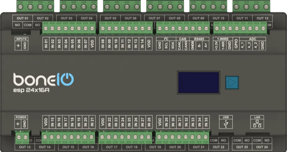
boneIO ESP 24x16A
You can buy the controller -> HERE
Leveraging the versatile ESP32 microcontroller and the simplicity of ESPHome, the boneIO ESP controller provides an incredibly flexible and easy-to-configure core for your smart home automations. With 35 digital inputs and 24 relay outputs, a single boneIO ESP controller has enough capacity to manage all the automation in an entire house or apartment. This includes lighting and heating systems, as well as controlling entrance and garage gates by providing a pulse to the drive. The boneIO ESP 24x16A is a specialized control unit designed to manage high-load electrical circuits. Equipped with 24 powerful 16A relays, each featuring its own, galvanically isolated COM terminal, it provides maximum flexibility and safety for controlling outlets, electric heating, pumps, or other high-power devices.
Key Features
- 35 digital inputs for connecting switches, motion sensors, contact sensors and others.
- 24 independent 16A relay outputs with full galvanic isolation (each relay has its own
COMterminal). for controlling sockets and high-power appliances. - 3 analog inputs for integration with analog sensors (e.g., light or wind sensors).
- Reliable network connection via an Ethernet port and USB-C.
- Wide expansion capabilities thanks to Modbus, I2C, CAN and 1-Wire interfaces.
- Built-in OLED screen for a quick overview of the device's status.
- Standard DIN rail mounting (12 modules).
Use Cases
Thanks to the high load capacity and separation of the relays, the 24x16A model is ideal for:
- Directly controlling electrical outlet circuits throughout a house.
- Managing electric underfloor heating or convector heaters.
- Controlling high-consumption devices such as pumps, fans, motors, or solenoid valves.
- Integration with three-phase power systems.
Technical Specification
| Feature | Value |
|---|---|
| Module | ESP32 |
| Power Supply | 24V DC |
| Power Consumption | 3W - 15W |
| Digital Inputs | 35 |
| Inputs Voltage | 24V DC |
| Relay Outputs | 24 (each with a separate COM) |
| Max Output Voltage | 230V AC / 30V DC |
| Max Output Current | 16A |
| Analog Inputs | 3 (A_1 - 0-5V, A_2 - 0-10V, A_3 0-25V) |
| External Interfaces | Modbus RS485, I2C bus, 1-Wire, CAN (for future use) |
| Communication | Ethernet 10/100Mbit, USB-C (for firmware installation) |
| Dimensions (WxHxD) | 216mm x 106mm x 57mm (without plugs) / 216mm x 123mm x 57mm (with plugs) |
| Mounting Width | 12 DIN modules |
| Weight | 800g |
Connectors and Components Description
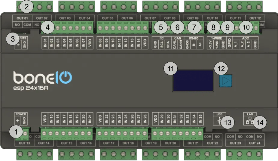
- Power Supply Connector (+/GND): Main power supply for the device (24V DC).
- OUT Screw Terminals (1-24): Relay outputs. Each output has a separate
COMandNOterminal. - Inputs control switch - inputs can be controlled either by + or GND.
- IN Screw Terminals (1-35): Digital inputs.
- I²C bus connector: I²C bus connector for connecting I²C devices.
- CAN bus connector: CAN bus connector for connecting CAN devices. For future use.
- Modbus RS485 connector: Modbus RS485 connector for connecting Modbus devices.
- 1-Wire bus connector: 1-Wire bus connector for connecting 1-Wire devices.
- GPIO connector: GPIO connector for connecting device which can transmit data to ESP32 GPIO. It's pulled down to GND.
- ADC connector: ADC connector for connecting analog sensors to get analog reading of voltage.
- OLED Screen: Displays key information about the device's status, such as IP address, connection status, or CPU load.
- Control Button: Located next to the screen, it is used to switch between different views on the OLED display.
- USB-C connector: USB-C connector for connecting to the computer to upload the firmware.
- Ethernet Port (RJ45): For connecting to the LAN.
Quick Start Guide
- Device Installation: A qualified person must mount the device on a DIN rail.
- Offline Verification: Connect a switch to input IN01 and a light bulb to output OUT01. Press the switch – the bulb should change its state.
- Network Connection: Plug a LAN cable into the RJ45 port.
- Accessing the Web Panel: Find the device's IP address (displayed on the OLED screen or in your router) and enter it into a browser to access the web interface.
Certificates
What's Next?
You can find detailed instructions on the dedicated pages. Go ahead and read it!