Advanced & Guides
Connecting Digital Inputs
Guide how to connect different types of devices to boneIO ESP digital inputs.
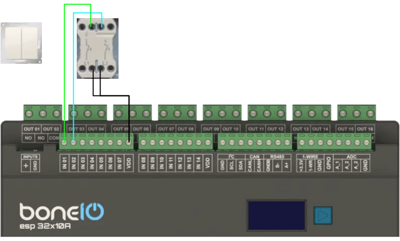
Momentary Switch
Digital inputs are used for connecting switches and sensors. By default, they are ground-controlled.
- Connect one of the wires from a momentary switch to the common
VDDterminal. - Connect the other wire to the desired input terminal (e.g.,
IN01). - Pressing the switch will close the circuit, which will be interpreted as an "on" signal.
Esphome snippet
binary_sensor:
  - platform: gpio
    name: 'IN_01'
    id: in_01
    pin:
      pcf8574: pcf_inputs_1to14
      number: 0
      mode:
        input: true
      inverted: true
    on_press:
      then:
- light.toggle: light_01- Multi-click configuration can be found on the multi-click page.
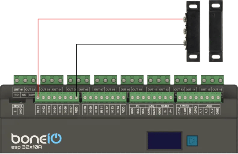
Reed switch
- Connect one of the wires from a momentary switch to the common
VDD(ground or +) terminal. - Connect the other wire to the desired input terminal (e.g.,
IN02). - When the reed switch is closed, the circuit will be closed, which will be interpreted as an "on" signal.
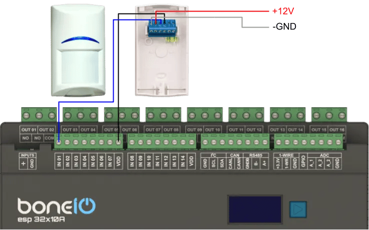
Motion sensor
- Connect one wire from VDD to one of the NC terminal in motion sensor.
- Connect second wire from NC terminal to the desired input terminal (e.g.,
IN01) - Connect 12V power supply to the motion sensor terminals.
- When the motion sensor is triggered, the circuit will be closed, which will be interpreted as "motion" signal.