Overview and Specification
Discover the boneIO Black Cover Mix, a versatile controller for 8 blinds and 16 lighting circuits.
boneIO Black Cover Mix
You can buy the controller -> HERE
Based on the powerful BeagleBone Black and running our custom software, the boneIO Black controller offers robust and reliable performance for your smart home. With 49 digital inputs 8 blind outputs, and 16 relay outputs, a single unit has enough capacity to manage all the automation in an entire house or apartment. This includes lighting and heating systems, as well as controlling entrance and garage gates by providing a pulse to the drive. It's also possible to control blinds though its build in blind outputs. The boneIO Black Cover Mix is a versatile controller that combines the features of a standard relay module with a specialized shutter controller. It features 32 relays, where 16 are paired with a hardware interlock for controlling up to 8 bidirectional motors (e.g., roller shutters), and the remaining 16 relays can be used for general purposes, such as controlling lighting circuits.
Key Features
- 49 digital inputs for connecting switches, motion sensors, contact sensors and others.
- Hybrid Outputs: 32 relays in total, including 8 pairs with a hardware interlock (motor protection) for controlling 8 roller shutters and 16 individual relays (10A) for general use.
- 7 analog inputs for integration with analog sensors (e.g., light or wind sensors).
- Reliable network connection via an Ethernet port.
- Wide expansion capabilities thanks to Modbus, I2C, CAN and 1-Wire interfaces.
- Built-in OLED screen for a quick overview of the device's status.
- Standard DIN rail mounting (15 modules).
Use Cases
The boneIO Cover Mix model is perfect choice for:
- Comprehensive automation of roller shutters and lighting in single-family homes and large apartments.
- Creating advanced scenes combining shutter control and lighting.
- Integration with an alarm system to automatically close all shutters when the alarm is armed.
- Integration with various sensors for advanced automation scenarios.
- Automating HVAC systems (heating, ventilation, air conditioning) thanks to Modbus support.
Technical Specification
| Feature | Value |
|---|---|
| Module | BeagleBone Black |
| Power Supply | 24V DC |
| Power Consumption | 5W - 18W |
| Digital Inputs | 49 |
| Inputs Voltage | 24V DC |
| Relay Outputs | 8 for blinds, 16 for lighting |
| Max Output Voltage | 230V AC / 30V DC |
| Max Output Current | 10A |
| Analog Inputs | 7 (Max 1.8V) |
| External Interfaces | Modbus RS485, I2C bus, 1-Wire, CAN (for future use) |
| Communication | Ethernet 10/100Mbit, Mini-USB |
| Dimensions (WxHxD) | 270mm x 106mm x 57mm (without plugs) / 270mm x 123mm x 57mm (with plugs) |
| Mounting Width | 15 DIN modules |
| Weight | 900g |
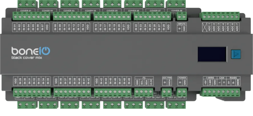
Connectors and Components Description
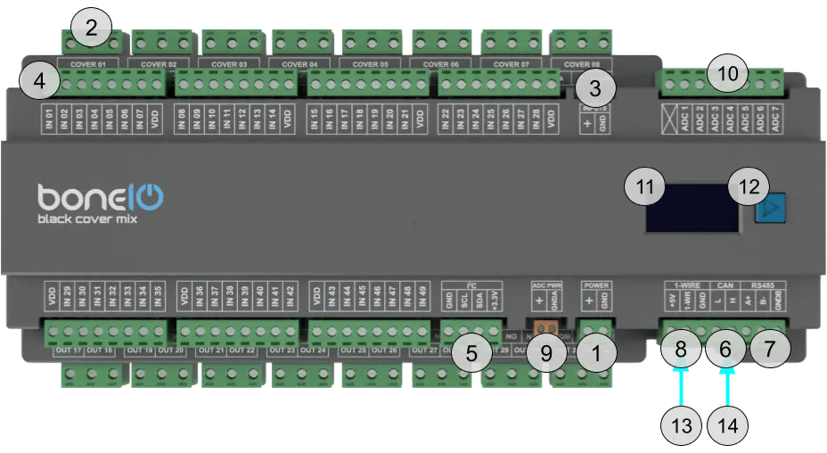
- Power Supply Connector (+/GND): Main power supply for the device (24V DC).
- OUT Screw Terminals: Top part Cover Up/Down for cover 1-8 lower part Relay outputs 17-32.
- Inputs control switch - inputs can be controlled either by + or GND.
- IN Screw Terminals (1-49): Digital inputs.
- I²C bus connector: I²C bus connector for connecting I²C devices.
- CAN bus connector: CAN bus connector for connecting CAN devices. For future use.
- Modbus RS485 connector: Modbus RS485 connector for connecting Modbus devices.
- 1-Wire bus connector: 1-Wire bus connector for connecting 1-Wire devices.
- ADC Power connector: Connector for powering up ADC devices.
- ADC connector: ADC connector for connecting analog sensors to get analog reading of voltage.
- OLED Screen: Displays key information about the device's status, such as IP address, connection status, or CPU load.
- Control Button: Located next to the screen, it is used to switch between different views on the OLED display.
- USB-mini connector: USB-mini connector.
- Ethernet Port (RJ45): For connecting to the LAN.
Quick Start Guide
- Device Installation: A qualified person must mount the device on a DIN rail.
- Network Connection: Plug a LAN cable into the RJ45 port.
- Accessing the Web Panel: Find the device's IP address (displayed on the OLED screen or in your router) and enter it into a browser to access the web interface.
- Estimate Shutter Movement Time: Measure the time it takes for the shutter to fully open or close.
- Connect the Shutter: Turn off the shutter's circuit breaker. Connect the shutter motor to the
Cover01 Up/Downoutputs. - Edit cover.yaml file: Set the estimated movement time in the configuration file and save it.
- Test the Shutter: Run the shutter from the web panel to verify the configuration.
Certificates
What's Next?
You can find detailed instructions on the dedicated pages. Go ahead and read it!